 |
Building a T20 Classic Racer
|
 |
Welcome to my racing page. This covers the conversion of a seized up rusty road bike into a very competitive Classic Racing Bike. I had wanted to race a T20 since I was 17 - over twenty years ago - and finally achieved my aim in late August 2002. It was hard work getting there as I knew nothing about preparing a race bike when I started this project. I didn't know who made the parts that I would need, what modifications were possible, even what was allowed in Classic Racing. I started by visiting the track, taking photos of race bikes, chatting to people and asking around for help and advice. I made many mistakes in my project and did things that with hindsight I shouldn't have. However, I got there in the end. This page covers the project from start to finish and although it is not fully finished I do try to update it as often as possible.
 I am pleased to announce, that I won the CRMC 250cc twins class in 2003.
I won the Championship again in 2005 and 2007 and was second in 2004, 2006 and 2008.
All the best
Adrian Baker
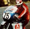
In action - Racing at Silverstone - September 2003
© Sport-pics.co.uk
1) Sponsorship
As my fund-raising gets going, credit will be given on this site to anyone who helps with the project. Whether you supply racing parts, cash, or just send me a few old spares, your name or company will appear on this page and elsewhere in the text. Please click here for a list of simple ways in which YOU can help.


|
Please support my sponsors -
Click on the logos now! |

|

You can now make donations, pay for services, pay for parts etc, with your credit card, online at www.t20suzuki.com. I have a Paypal.com account which means that I can take credit card payments from anyone, anywhere in the world. The logo below is the one to click if I have sold you something and asked you to pay me by credit card. (Alternatively, if you want to send my race team some funds because you have enjoyed my site so much, just click below and make a donation!)
This is a great system to use if you are buying or selling goods over the 'net, such as T20 parts advertised on my Noticeboard. All payments/debits come through to your credit card in your national currency with only a very small commision charge. You can be paid online with PayPay in dollars, pounds or Euros. Want to find out more? Go to Paypal.com.
Big thanks must go to Lea Gourlay - Britain's top Classic racer - who has become a close friend over the past two years. Lea has transformed my bike, rebuilt my crankshafts, tuned the barrels, set it up on a Dyno, modified my swing arm and given me countless pieces of advice. I really can not thank him emough. Watch out for changes to this page outlining some of the work he has done.
Thanks also go to:
John and Mark Hullah - for massive help in bike and caravan preparation both before and at meetings.
Mary Tappenden - for sponsorship, encouragement and help in the workshop.
Eric 'Spanners' Blakely - who has raced a t20 for years and has loaned me some parts, given me advice and has helped me so much with bike preparation and set up. Eric has been absolutely invaluable in the pits.
A.M. Philpot (Hard Chrome) Ltd for a healthy discount given to me - Thank you very much. Phone them on 01582 571234 for stanchion rechroming.
Bishop's Stortford College, where I work as a Physics teacher, but spend much time in the CDT department getting parts brazed, made up, turned down etc (Thank you Phil for all the help)
With over 80,000 hits on this site so far (generally from bike owners of similar interests) there is a lot of potential to get your product (or name) known around the world. Please get in touch. Likewise, if you get in touch with ANY of the contacts given on my site, please tell them where you heard about them from. This helps me, help you, help them!
Back to top

2) Frame
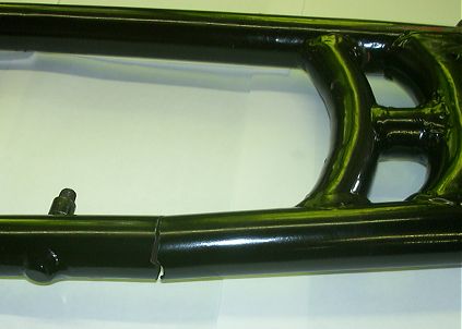
Whilst getting my frame to the final stages, I picked up an unfinished T20 race bike project. This had a frame that was modified by Andy Bacon (Abcon), was all finished off, painted up and ready to go. I decided to put mine to one side and use this one - not necessarily because it was better, but because it was finished! The later pictures (with painted frame) showing the fairing mounts and the headstock bracing are therefore Andy Bacon's work, not mine. All the unpainted frame pictures show my work. I will be finishing off my frame soon and will eventually have TWO complete T20 race bikes!
It is actually possible to buy a replica frame and swing arm for a T20. These are made by Tony Baker and are far superior to the originals. However, part of the fun for me is getting my old bike and parts prepared for the track, and although, funds permitting, I would certainly consider buying a replica frame, my original intention is to convert and strengthen my original.
I first cut all the unnecessary lugs and brackets off my T20 frame with a hacksaw, and then used a grinding tool to clean up the bits left behind. The frame was now ready to be modified. I took a picture of a TR250 frame, along with a quick sketch, to Harris Performance Products. They cut and bent some tubing for me so that I could 'TR250' my frame.. I then had to cut, shape and jig the bits about and braze it all together!
Here is the front tube, cut to size and ready to braze into position. This was a modification that Suzuki made to later frames and if your frame is late '68? onwards, you won't need to do this.
When the engine bolts are tightened up normally, the twin downtubes are pulled together by about 3mm. You must therefore braze it up with the engine firmly bolted in, otherwise you will bend the frame when you tighten it up later!
|
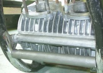
Ready to braze
|

Centre piece not in position yet
|
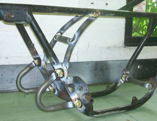
This pic shows the rear strengthening bars taped into position with insulating tape. The centre bar of the 'H' shape is not yet fitted. This is how the TR frame looked and I think it looks really nice. However, I have been advised by Kevin Strowger that it is far better to use straight bars as that makes a stiffer frame. I'm happy as it is though, particularly as I had just had the tubing bent when he told me!
|
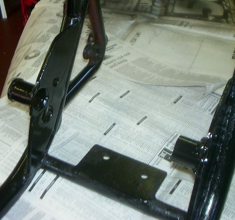
Below you can see how the frame looks now that most of the braizing is done:
|
All of the main frame strengthening is in place as are the rear footpeg loops (see text below). However, the headstock can't be done until I get my TR250 replica petrol tank. This will fit onto lugs that will need to be fixed onto plates either side of the headstock. I will then assemble the rolling chassis so that I can work out how to make the fairing fit. This will also involve braizing brackets to the frame. Only when this is all done can I finally finish off and paint the frame in its final (as yet undecided!) colour scheme. |
|
 |
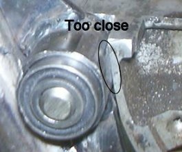
A problem arose with the rear footpeg loops - when I had them all in place ready to fit, my friend who was about to braze it all up pointed out that the gap for the swing arm wasn't very big, "perhaps you had better check it out with the swing arm fitted" he said. Good point! After fitting it, we found that the swing arm was touching both of the rear loops and wouldn't be moving up and down much in the future!
|
If you look closely, you can see how we got around the problem. I re-profiled the loop ends so that the outer edge of the footpeg loops was flush with the outer side of the frame tubes. This shifted each footpeg loop outwards by about 2/3mm, and gave us the necessary clearance. To increase this further, the inside edge of each loop was filed and flattened slightly where it had spread outwards whilst being bent. The clearance is now fine.
If I was doing this again though, I would use thinner, and lighter tubing.
|
| |
This is the headstock bracing. This is on the frame that Andy Bacon modified, not the one that I did. The tank mounting is a 11mm (ish) diameter tube going through both bracing pieces and welded in place to strengthen the lot. The rubbers are from a small Kawasaki model - my local dealer had them in stock but wasn't quite sure what they were from!
The Rex Caunt Ignition control box is fitted inside the bracing pieces. It was awkward to fit it there, but it is now well out of the way and securely fitted.
|
| |
You can also see the Rex Caunt
Ignition Control box
|
Back to top
3) Rubber Mounting the Engine
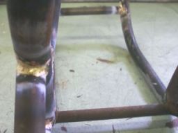
During the 2004 race season my crankcases cracked around the rear left hand mounting. At the end of the season I stripped the bike down and the frame had cracked quite badly on the front two downtubes, all around the engine mounting brackets. I had all the cracks welded up, but wondered if rubber mounting the engine would help me stop this happening again. However, I didn't have time to do do this, so after repairing all the damage, I raced it through 2005... and both front down tubes cracked again! They were almost in two parts at the end of the season, so this time I had no choice - rubber mounting here I came!
Many T20s out on the track have had this modification done and the best way of doing it is use Yamaha TZ engine mounts. You can get these in 8mm or 10mm internal diameter and I went for 10mm front and back. The original T20 front engine stud is only 8mm in diameter, but I had already drilled this out and was using a 10mm stud, so I continued to do so. I intended to make the holders very strong and so once the front and back mountings were in place, I'd cut off the bottom mounts as they would not be needed any more.
One of my main design principles though was to not have to modify the engine in any way at all. I wanted to be able to fit any standard set of cases, spare engine etc straight from an unmodified frame into this one. That made the job much harder to do, but it will hopefully make life easier in the future.
How I did it.
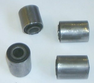
Here you can see the TZ bushes I used. (If you want some, they are Yamaha Part Number 102-22123-00).
These look a bit second hand, but this is just because they had a hard life being used in making up the mountings.
The rubber mountings have a very thin outer metal casing and this will have to be slotted into a holder of some kind. It needs to be a light interference fit, with an end cap to prevent the bush sliding straight through the holder. The engine must be bolted through the centre of the bushes and not touch the frame or mountings, and the frame must only touch the outside of the bush. To complete the job I will need to make some spacers too (see diagram below).
|
|
 |
The first job was to turn down some mild steel and then drill it out to a size close to the outer diameter of the bushes. I then cut this tube into appropriate lengths and carefully bored each holder out on the lathe to make the bushes a light interference fit. I probably was overly careful on this though as you will find out later on.....
The front engine mounts
Each of the two holders had to be shorter than the bush by a couple of millimetres so that the engine bolts wouldn't touch the mounting. I had made the two tubes of the correct size and then had to weld a piece of thin steel on the end of each to prevent the bush from sliding through. Once this was done I turned down the weld and excess plate and also bored out the end with a 19mm drill, so leaving a welded on 'hoop' at one end that the bush could push against. I didn't take any photos at this stage as I was in a rush to get the job done, but the diagram below shows what I did (I hope!).
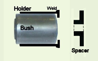 The diagram above also shows the spacer that I had to make for each of the front bushes. These press up against the cranckcases and bolt tightly to the centre of the bush. As the engine vibrates, the spacer allows the engine to move about with respect to the frame.
I said above that I had "carefully bored each holder out on the lathe to make the bushes a light interference fit". However, once I'd welded on the end cap, I realised that I had been overly careful - welding on the end had distorted the holder and the bush no longer fitted in. I then had to spend ages with emery paper and a dremel taking off the high spots to make them fit again. (After welding the holders to the frame I had the same problem again!). The distortion wasn't too bad though, so perhaps I hadn't wasted my time after all.
To weld the holder to the frame I had to make up some brackets. I bolted the engine into place using the rear and bottom mounts, (having previously cut the front ones off) and tried to bolt the holders and bushes to the front of the engine.
NB You MUST remember here that dual diameter spacers are needed between the centre of the bush and your engine. When bolting it all together, put a 3/4mm thich large diameter washer between the engine casing and the bush holder to leave a space for the spacers that you will need to prevent the engine touching the bush holders and frame tubes.
However, a problem arose... the Left hand holder fouled the engine casing and I couldn't get the stud through. Damn! Maybe I should have used the 8mm mounts after all.
My plan had been to rubber mount the engine without ANY mods needed on the casing. However despite milling down the side of the holder to help it clear the engine casing, I also had to file away some of the crankcasing to get it all to fit. This wasn't what I'd planned, but my 'alterations' worked and it all fitted correctly.
I've seen some T20s with great big cut-outs in the casing here to make way for this bush, but I had to take very little off the casing and holder to make it fit. You only need a clearance of a mm or two, so don't go mad here chopping up your casing.
|
|
 |
I now had the engine in place and both front bushes and holders bolted to the engine. From this I could make cardboard templates of the mountings I would need to weld the holders to the frame. Having made these up, I got some 5mm thick steel plate and bored a hole in it which had the same size as the outer diameter of my bush holder. Then, by cutting the shapes I needed away from this hole, I made the four brackets I needed (two for each side), each which fitted nicely up against the round holder, and against the frame. I tacked this all in postion with my arc welder (getting the rubber bushes rather hot in the process) and hey presto, my front mounts were ready for welding.
All tacked up ready for welding
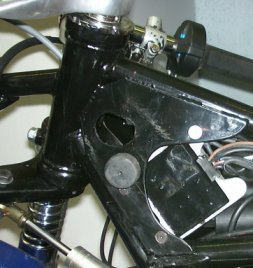
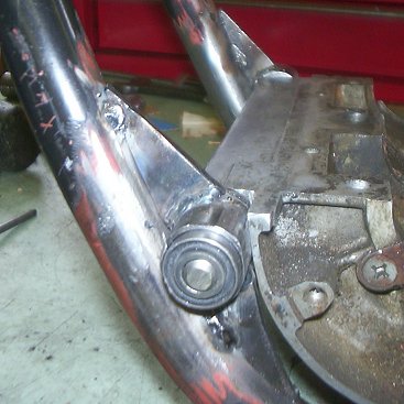
In the pictures below you can see the finished job both with, and without the engine fitted. In the picture with the engine in place you can't see the spacers that are fitted between the bush centre and the engine, but they are there.
| |
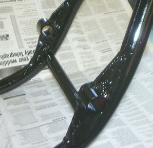
After Painting |
|
All bolted up |
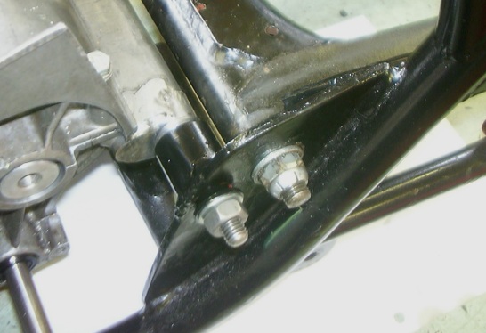
The rear engine mounts
The left hand side
The front mountings had been tricky to get right and took me a lot of time to get right. The back ones also would give me difficulties,as although the left hand one was easy to do, the right hand side was very difficult. The left hand side spacer is easily fitted in place where the present spacer between the frame and the casing fits. To do this, I had to first turn the rubber mounting bush down on my lathe as it was too long. you need a sharp parting off tool to do this correctly.
I then put the bush in its holder, added a steel washer between the bush and the casing, and bolted the engine in place. I had to weld the holder to the frame and this was easy to do as it was pressed up against the frame plate where the engine stud goes through. However, the only way I could get this to line up correctly was to tack the holder in position (with my arc welder) WHILST the rubber bush was in place. As you can imagine, this smelt revolting as the rubber melted. I had to throw this bush away afterwards and then buy and turn down a replacement for it.
Once this was done I had to drill out the frame plate where the engine stud went through. As the outer side of the bush was pressed against the frame, the engine stud had to bolt to the centre of the bush WITHOUT touching the frame. I used a spacer similar to the ones used for the front mountings, but this time this was used 'in reverse position' held firmly agains the stud bolt.
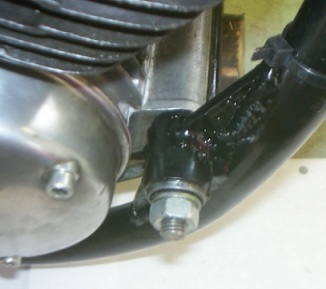
Here you can see the finished job, with spacer in position, all painted up and bolted together. The clearance betwee the frame and the spacer is a couple of mm.
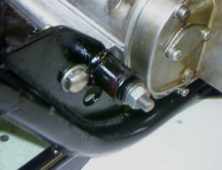
The right hand side
This was the mounting that I had most worried about doing as I couldn't immediately see how to do it. The engine presses hard against the frame plate here and if I was going to rubber mount the engine, I couldn't have the engine touching the frame. Also, as the left hand bush was held on its outside edge by the holder, this one would have to be too to prevent the engine from moving sidewards. I therefore needed to mount the holder on the outside of the frame plate, and insert the bush from the inside.
Once again the only way to line up the holder before welding was to do so with the bush in place. So I bolted the engine in place and tacked the holder in place with my welder. I then had to grind out the frame from the inside so that the hole in the frame plate allowed me to remove the burnt bush. Finally to prevent the engine from touching the frame plate I ground away a couple of millimeters of the plate to give me some clearance.
You can see what I did in the photo below:
The mountings look very odd when in place, but in both cases the bushes push in from the inside, so the engine is held firmly in place. On the outside of both of the bushes a spacer is needed as described in the section above. You can see the engine all bolted up in place, with spacer, in the picture below:
So there you are, that is 'all' there is too it. I chopped off the bottom mountings, painted the frame, replaced the engine nuts with Nylock ones and away I went. It took me many hours to do, but it it really does make a difference. When you ride the bike the vibration is still there but is SO much less. I was worried about clearance as the engine moved about, but the TZ bushes are high quality and barely let the engine move at all. Hopefully I'll have no more cracked frames and cases.
Give it a try!
Back to top
4) Swingarm
The Tony Baker replica swing arm is two inches longer than the original. After talking to guys that race these bikes, it seems that this is a poular modification. So, I had to sort out mine... As you can see in the picture, a two inch extension has been brazed in, with thinner strengthening tubing running inside each piece.
This was done by my good friend Graham Huckle at HuckleHeath Coachbuilders (Links Page).
|
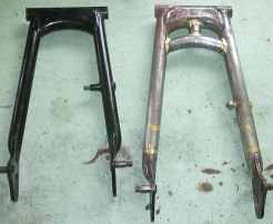 |
Another weakness of the T20 swing arm for racing is the puny size of the pivot bearings. The T250 or GT250 swing arm have larger diameter ones and are a good modification. However, I want to use original bits where possible at first - I may upgrade this when I know how well (bad?) it handles on the track!
Problems on the track .... (Update after two race meetings)....
Oh dear, it didn't quite work as planned. The handling was awful due to the rubbish shocks I had fitted, but also there was a weakness in the swing arm. The torque arm bolt was replaced with a different one as the original was now 2 inches further away from the wheel; but, by grinding off the old one (and the weld around it) the swing arm was left with a large diameter bolt bolt inside the swing arm, without lots of weld to support it. This led to a 'small' crack appearing.
I had competed in four races at Anglesey over a weekend, but in the last race, a plug fouled up and I pottered round slowly just to get a finish and some points. Just as well really, because when I got back home I noticed the damage shown above - one more bend at race speed and I would have been in big trouble!
So, if you have done the same mod as me, DONT grind off your old torque arm bolt!!!!!
After repairing the damage (I sleeved it and rebrazed it) and fitting some far better NJB shocks, the bike handled far better. In fact at the next meeting at Cadwell Park, I managed to beat Dave Brown on his T20 (see Dave in the 'My first Race meeting' section)
Update 2005
My swing arm mods just didn't work out. Although the bike worked well with a longer swing arm, it broke once and cracked a couple of times. I was considering where to get one made that would be better when in stepped Lea Gourlay who said he'd make me one - "no problem"! I gave him an old, unmodified swing arm and he added two inches to its length. However, he didn't add all the extra bracing that I'd had before - "no need - I've done it correctly" he said, and he was cheap too! I have now done nearly two seasons on this swing arm and I've had no problem at all since then. A superb job that fixed an ongoing problem - thanks Lea!
Back to top
5) Wheels and Brakes
Front Wheel choice
I had to decide on what wheels and brakes to use. On the front the choices were, the original front end, a GT750 Suzuki 4LS front end (a common choice, but heavy), some exotic 'Fontana' type replica (very expensive), or various options like Grimeca, Manx Norton, Robinson, etc. The original brake is fine though, according to Martin Crooks of Crooks Suzuki:
|
"Although there are plenty of options on the front end, I used a standard T20 front end with Ferodo AM4 linings. Most people say this is no good, but it was OK when I raced the Manx at an average lap speed of 91mph. (Although it was fading quite bad towards the end of 4 laps!)"
|
Maybe his lap speed was so high because the brake was fading! Despite Martin's experience, I decided to go for a GT750 front end. There were three main reasons for this:
- I have a GT750 front end fitted to my '59 BSA A10 (it makes purists cry...) and have been very impressed with it.
- My original forks are in very poor condition.
- I remember going through a hedge on my T20 years ago due to brake fade, and I don't fancy a repeat performance!
|
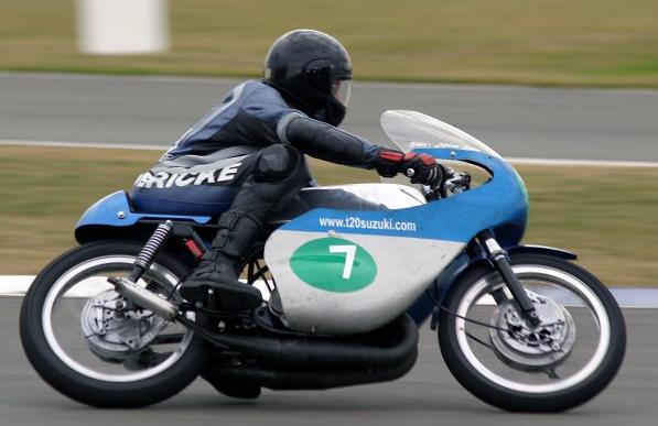
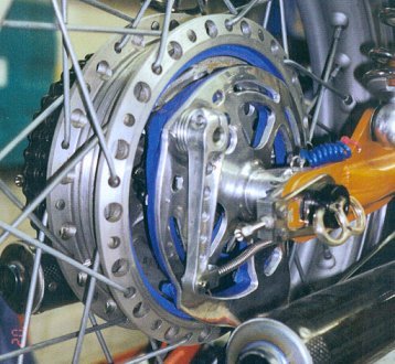
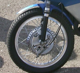
The T20 racer pictured here has got a GT750 front wheel - it looks good too! The bike belongs to Don in the USA. I got hold of a front end from Straightline Racing, although it came without the break arms and linkages. (I have tried a couple of times to get some from them, but no joy yet). I have polished both the front and rear wheel hubs as well as the two Alloy rims. They have now been spoked up and look stunning!
|
|
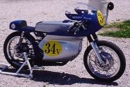 A T20 racer from the USA
|
The next stage was to get my brake shoes re-lined. One of the best companies in the UK to offer this service is Supreme Motorcycles. I have used Supreme in the past to reline the GT750 front end that is fitted to my BSA roadbike. They did a superb job and I can squeal the tyre on my BSA at 70mph with one yank of the brake lever! Supreme have also kindly offered me some sponsorship for my T20 racebike - thank you guys. I sent the shoes and brake plates to them, but they needed the wheel as well to cut the linings to size. Turnround on this service was within a week and as you can see below, they have done a superb job.
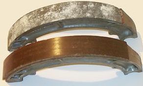
My old linings - one missing!
|
|
My new linings - excellent!
|
The linings are non-asbestos race ones, and considering how good my BSA stops on road linings, I think that my T20 should stop quite well indeed!

I highly recommend the work that Supreme do; Click on the image above, give them a phone or Email them for a quote. (Don't forget to mention www.t20suzuki.com!)
Update:These brakes are superb on the track. It took a while to get them set up right, but after every test session, I took the front wheel out and took all the high spots off the brake shoe material with fine emery paper, to help it bed in. At my first race meeting at Lydden, I was pleased with the brake at first, but as it all bed in nicely, I was even more impressed at the stopping power. Nothing seems able to outbrake me, but I outbrake lots of other riders! I have not suffered from brake fade under any conditions, and am very pleased with both the Suzuki front wheel, and the work that Supreme Motorcycles did.
Getting the front wheel to fit the forks that I eventually used is covered in the section below.
As my racing skills improved and I got quicker and quicker, it soon became clear that the handling of the bike was awful - the front end pattered and bounced around like a pogo stick!
There are two main reasons for this. First, the front wheel and hub are far too heavy, and secondly, the T20 forks are rubbish! They don't have any damping at all. So, what could I do...
(My modifications to the forks are in the next section)
Weight loss program
I had quickly assembled the bike to get me racing, but had not bothered to reduce any weight from the standard hub. So, Off came the front end, and in stages, over the season, more and more material was removed... Spindle drilled through (first 5mm, then 6mm drill through most of it up to near the thread), brake plates turned down and milled out, brake shoes drilled, hub drilled, brake pivots drilled.... It goes on and on.
Below you can see the modifications I made to the hub and brake plates:
The holes between the spokes are just over 14mm in diameter. |
|
I removed well over 200g from each brakeplate. |
I've added 6 holes...Shall I do 6 more? |
|
This is inside the hub itself. Suzuki drill one of the holes per section as standard (6 in all). I added to this by drilling another six.
I was worried about doing this, but thought that it would be OK.
It has been so far, and some other riders I have spoken to have drilled another hole in each segment at the bottom of each 'triangle'. I may do this for next season... Has anyone ever done this and had one break on them?
I know one rider who turned the cooling fins off the outside of the hub, and another who turned down the steel linings to reduce weight. I'm not sure how radical to go yet.
|
This did make a real difference to the handling and when I finally replaced the front tye with a smaller KR825 Dunlop, the transformation was complete. It is still a little too heavy but is SO much better than it was.
- Update end
Rear Wheel choice
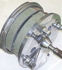
On the back there is no problem - use the standard rear wheel. Its the same as fitted to the T/GT500 and is certainly up to the job. I didn't get my shoes relined as I had a new pair of EBC shoes on the shelf, and the original T20 brake is excellent as it is. So that was it, all standard.
However, as you can read in my 'Track Testing' section and in my 'My first Race Meeting' section, problems did arise. The rear brake overheated severely (due to me being too heavy footed), the bearings came loose, and the brake plate expanded and made contact with the wheel. Nasty!
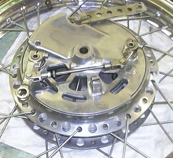
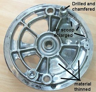
This meant some more work had to be done. First of all I mounted up the brake plate on a lathe and turned down the rim that is supposed to keep out the water. Then I faced up the plate so that the gap between it and the wheel was much bigger. Some people go really radical on this, but I just wanted to stop the problems that I had experienced.
Next I drilled some air holes to get the air flowing through the hub. I had borrowed my good friend Eric Blakeley's rear wheel for the race at Lydden, so I based the drilling pattern on his, as he had successfully used his wheel for many years without any problems. This is what my rear brake looked like when I'd finished:
|
|
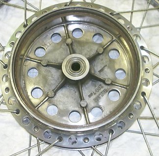
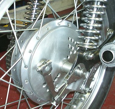
Here it is all bolted up. On taking the brake plate off after a race, you can clearly see the air and brake dust flow marks out of the rear drill holes - it works! I have had no problems with overheating since.
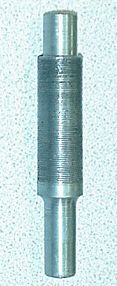
You can also see here how I turned off the end of the spindle, drilled a hole through for a silver steel rod to help hold it. and also drilled through the centre of the spindle as far as I could from both ends. I managed to save a massive 63g! Not much I know, but you want the lowest unsprung weight (the bits that move up and down) possible as it helps the suspension to react better, improving the handling.
|
So how far can you take weight loss? Some people go VERY radical. Kevin Bentley of Teeside send me some photographs of his bike. Have a look at this rear wheel then!
I think that this looks lovely - mine might end up this way too eventually.
Back to top
6) Shock Absorbers
I had originally used a pair of Hagon shocks on my bike. I had bought these as part of a 'job-lot' of T20 stuff but the handling with these on was appalling. However, I have no idea what these shocks were made for, or what they had been used on so don't judge Hagon shocks just by this!!
I quickly replaced these with NJB racing shocks as they were cheap and I'd seen others use them. These made a real difference and although the bike has never been a great handler, my laptimes certainly improved with these on. They were built for my weight and bike and I have no real complaints with them, other than the total lack of adjustment. However, after a season of use they were certainly not working as well and the action was not as smooth - I suspect that the pistons inside were scuffed and pitted. Over the 2004 season my speeds improved, but the increase in speed, combined with the deterioration of my shocks, made the handling a big issue. My bike was going like a rocket for the 2005 season, courtesy of Lea Goulay's tuning, but the handling was causing me such grief that I was losing races and becoming a danger to myself and others! I even began to not enjoy riding it at times. Obviously something had to be done. The front end was rubbish (no damping) and the rear not much better. To sort out the rear I invested in a pair of Falcon shock absorbers. Not the cheapest, but from what I have heard and seen on the track - probably the best.
You can see them below fitted to my bike:
| |
 |
|
Aren't these lovely?
They really are superbly designed and built shock absorbers. They are aluminium bodied and very lightweight. Also, as you can use them either way up, you can lower the unsprung weight by having them 'upside-down' as I have them fitted here.
These were made to the length I specified and supplied with 50lb/in springs. Falcon were really helpful in working out what I needed and they offered to swap the springs if necessary for different rated ones. They also offered to set them up exactly for my weight and bike if I was prepared to take the bike to them.
I fitted the shocks shortly before a Cadwell Park meeting and was amazed at the diference - they are a superb shock absorber and I just couldn't believe the difference. I was going into bends the same speed as before but managing to come out he bend a long way from the track edge. I had to re-learn the course!
The standard setting was a little soft so I adjusted the spring pre-load and they were spot on. Excellent stuff!
|
Fitting the shocks was a bit of a problem and if you look carefully you can see that they do not have nuts holding them on. Falcon make these shocks without a centre bush in the ends - just a rubber fitment. The idea is that the rubber slides round the mounting on your frame and swing arm so that the rubber doesn't add its own damping. I was told that an ideal way to fit them was with two thin nuts tightened together just touching the rubber bush. However, these shocks are much wider than my originals (I had removed some of the excess thread on my frame too!) and so I only had a couple off mm of shaft sticking out. I was completely stuck as to what do do next when a friend phoned and he suggested 'R' clips and lockwire. Thanks Alan! I quickly drilled the shafts, fitted the pins, wired them up and I was done.
I'll probably drill out he shafts in the winter and have an end bolt, but for a quick solution, the clips were ideal.
One of the joys of the Falcon shocks is that they are totally rebuildable. The factory supplies all parts and will happily rebuild them for you if they suffer crash damage or wear. If you do fancy buying some, I'd recommend phoning (or emailing) the company as they are really helpful and will talk you through the process of buying exactly what you need. (Please don't forget to mention this website either if you do contact the company)
I really do recommend Falcon shocks to you - they are a superb product.
Back to top
7) Forks and Yokes
The original plan.
I intend to use the GT750 forks that I got with the front wheel. These aren't strictly speaking eligible for Classic bike racing. However I have no better ones, they fit (or will do), and they are allowed in most Classic races - not the Classic Manx though. The GT 4LS front wheel does fit into the original T20 forks with a bit of modification and this is an option used by many racers. Others use Cerani forks which are 'legal' for all classic events. However, I don't have a useable, or even repairable set of T20 forks (read 'Restoration' section to see why) and so the GT forks are a good option for now. As for my T20 roadbike, the stanchions were straightened and rechromed by A.M. Philpot (Hard Chrome) Ltd. (Nationwide collection and delivery service). You can see the quality of their handiwork on my 'Restoration' page. A superb job was done on the GT forks and a healthy discount given to me because of this site - Thank you very much. Phone them on 01582 571234
To convert the GT yokes to fit the T20 frame should have been easy. However, this was not the case...... The GT central stem has the same thread on as the T20 one, but is about 1 inch (2/3cm) longer with a different end fitting for the top yoke. The easy solution is to get a 25mm die and run it down the yoke to cut the thread down to the required height, then turn down the stem top in a lathe to the correct length and to the correct diameter for the top yoke end fitting.
I managed to get the correct die and ran it down - success! However the thread was a little tight so I ran it down again. On the way back up it 'picked up' some material and destroyed all of the new and original thread - Bloody great. To resolve this, I chopped off the end of my yoke stem and resolved to make a new end piece. First the whole yoke was mounted in a lathe and the centre of the stem bored out to make it bigger and concentric. (It's not essential to do this though). Next, I had to make a new end piece...
|
 |
|
I know that there are many different solutions to my problem, but this is the way that I did it. On the left you can see the end piece that I made. A very helpful toolmaker showed me how to do this and I am proud to say that I cut the thread on a lathe myself!! I could have used the die that I had, but decided against it after my earlier experiences. The thread is the same 25mm x 1mm thread as before, as I intend to use the original T20 threaded top bearing holder/adjuster. Both ends have an M8 thread in them, the top one for the top yoke bolt, the bottom one so that I could use a long bolt to hold the spigot tightly in position when I brazed it up. The top of the yoke stem was chamfered to match the chamfer on the spigot bottom, but when they were assembled, a 3-4mm gap remained for the braze to fill. |
The yokes are now brazed up and ready for fitting....
Ready for assembly..
|
|
Ready for Brazing
|
I got some taper-race steering head bearings from Crooks Suzuki who have them in stock for the T20. They are a different size to all the rest of the T/GT range so don't buy after-market ones for a GT250 hoping that they will fit!
Iam using the GT750 alloy top yoke, but have modified it by cutting off the handlebar lugs and getting the holes that were left behind welded up. I will post pictures of this shortly......
Update - What actually happened...
I could delete all my earlier work above and just put up what I actually did. However, this site is a 'warts an all' account, so here is what happened next.
I lined up all the yokes, forks and wheel and thought to myself - "Oh dear, this is not going to work". The trouble was, the forks were far too big and heavy for the bike. I had fitted some years ago to my BSA A10 and they looked and worked great, they looked good on T500's and similar bikes and I thought they'd be OK for this one... Wrong!
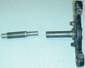
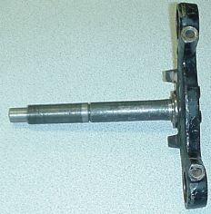
So now what! Well, many other riders use the original set up, but as I said above, I hadn't got a good pair of forks to use. Just I was wondering what to do next, I purchased an unfinished racer project, in bits, as mentioned in the Frame section above. This had some completely refurbished, original T20 forks with it. So, the plan changed and I fitted the T20 forks and yokes, along with taper race head bearings. The only modification the forks need for the GT750 4LS hub is for the brake plate lug on the right hand fork leg to be cut off. This I duly did.
The T20 spindle is the same diameter as the GT one, and the wheel fits in to the forks reasonably easy, but is too wide. To remedy this, I milled down each brake plate. I carefully measured how far from the centre of the forks my rim was, and then milled off this much (it was 5mm I think) from the LEFT brakeplate , as this one is tight up against the fork leg when properly fitted. The twin diameter spindle pushes up to the brake plate on the right hand side, and allows the forks to be aligned properly before tightning up. I took a couple of mm more off this brake plate than the left one to allow some flexibility in lining it all up. On bolting it all together, my wheel rim was within 0.5mm of the centre of the forks - not bad! I used the original GT750 torque arms, but cut them down as they were too long.
As mentioned in the section above, my bike handled really badly. The weight removal on the front hub really helped, but the forks were rubbish too. T20 forks don't have any damping mechanism at all as standard and it is very difficult to modify them.
A sidecar racer that I met at a meeting, Bob Dowty, used to race a T20 and he lent me some stiffer springs that he had had made up for his bike. He also recommended using SAE80 gear oil in the forks too. Well, I thought I'd give it a go. I put 200cc of SAE90 (I weigh more than Bob!) gear oil in each leg and fitted the springs... I was amazed at the difference. I wouldn't say that it had any more damping, but it made a massive difference.
At Cadwell Park and at Croft I had two great meetings with the bike handling really well. At the last race of the year, at Silverstone though, the bumpy bend at the end of the start/finish sraight still caused me big problems. Yes, the handling has been transformed over the season, but there is still work to be done. I intend to get different front forks for the 2004 season..... Watch this space!
Back to top
8) Cylinders and Engine tuning
A standard T20 engine develops 29bhp. If you want to be competitive in Classic Racing, you need to nearly double this! This takes some doing.
So far I have tried three different sets of cylinders, each done by different tuners. Below is my report of each. However PLEASE TAKE NOTE, all tuners prepare barrels in the way their customers ask for, so direct comparisons are unfair unless exactly the same was asked for, which was not the case here.
1) Fahron tuned cylinders.
Ron Phillips, the proprietor of Fahron engineering, has been tuning T20s for a very long time. His barrels have won many races and championships, and are a favourite of many Isle of Man racers. Ron makes 5 port and 7 port barrels, used for short and long circuits respectively.
I picked up some unused Fahron barrels through this website and as such have no idea what the original customer asked for. These were Ron's 5-port barrels. These have an extra transfer port cut into the liner. The pistons used (CR125) then have a small slot milled in each, that line up with this port. The theory is that you get an extra transfer port, and also the piston crown runs cooler due to the better air flow through the piston underside. The piston machining can be seen below:
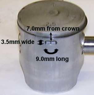
CR125 Piston with slot
These are the cylinders that I first used and I was impressed at the raw power. However, they are SO peaky and difficult to ride on a short twisty circuit. The engine coughs and splutters at anything below about 8000rpm and then BANG, in comes 30+ bhp that quicky rises to 46bhp @ 10,200rpm. You struggle to rev past 10,500rpm and so your rev-range is very restricted. I tried many different carb settings and I just couldn't get any drive at all lower down. If you ever drop below 8000rpm, the bike splutters and only a dip of the clutch or a change down will get it to pick up - even in the lower gears. What is also noticeable about these is the amount of 'blow-back' through the carbs. The rear of the bike is totally covered in Petroil mix after each race.
Looking at the porting of the barrels I was surprised at how low down the inlet port was - a good 5mm lower than any others I have used. This makes the transfer time very short and I'm sure is responsible for the blow-back and poor performance from 7-8000rpm. Having said that though, if you are prepared to dip the clutch a lot and can ride a peaky bike, then you sure can go fast. I've set my fastest lap on a couple of UK circuits using these barrels and so they certainly do the business.
2) Stan Stephens tuned cylinders
|
|
Stan Stephens kindly offered me some sponsorship to get my T20 racebike prepared. As they have previously tuned many T20's, including a Classic TT winner, I was very pleased that they were so keen to offer to help. Stan Stephens tuning has an excellent reputation in the UK and they are very highly rated for both two and four stroke work. |
Stan Stephens tuned my barrels using RG250MK111 pistons. These had been recommended to me and Stan had used them before so it seemed a good choice. I also specified 30mm carburettor size and Stan thought that this was a good choice for short circuit racing.
When I got my barrels back I was very impressed with the quality of the workmanship - the ports were beautifully opened up and finished off. A real work of art.
On the track I was also impressed. The engine was transformed. The engine ran cleanly from as low as 7000rpm, picked up at about 7700rpm and revved all the way to 11,000rpm. Now that was different! The engine felt less powerful than with the Fahron barrels, but as I never managed to Dyno my engine in this state it is hard to say if this was the case or not. Peaky engines always feel more powerful due to the way they pick up, but of course, this doesn't mean that they necessarily are so. I did find that my top speed was not always reached as soon on long straights, but I was quicker through the twisties due to the easier ride.
As a novice rider I found these cylinders superior to the Fahron ones, as I'm sure would most novice racers. This was the the spec I had asked for from Stan and he undoubtedly achieved what I asked for. In comparison to the Fahron barrels, I never quite felt as if I was going as quick, but I was - on some courses I was slightly slower, but on others slightly quicker. However, as I'm sure many experienced racers will tell you, it isn't the bike that does a fast lap, it is the rider! Both solutions, Fahron and Stan Stephens, did the job of making my bike capable of winning races.
3) Lea Gourlay tuned cylinders
Lea Gourlay is without a doubt Britain's fastest Classic Racer, and his performances on the track are at times beyond belief. I have been fortunate to become good friends with Lea and have found, to my great benefit, that Lea is not just a fantastic rider, but is also just as talented when it comes to the tuning, setting up and preparation of race bikes - particularly so two-strokes such as the TZ Yamaha, and the T20 and T200 Suzukis featured on this site. Lea tunes and prepares Team Spencer's t200 Suzuki and has overseen its development from an also-ran in the class to an unbeatable Championship winner.
Throughout 2004 I got beat on the track by one or two particulary fast T20 Suzukis (and also by one or two slower ones ridden by better riders, but that's another story...) and I wondered if my bike could be developed further. Lea offered to tune some cylinders for me and help me get the bike sorted out - particulary so as I had little experience of fettling a bike to get the most out of it.
Lea decided that 34mm carbs and some radical porting was in order. Everyone else I had spoke to in the past had assured me that 34mm was too big, so I was a little apprehensive, but Lea was convincing... and as it turned out, he was right!
The ports looked HUGE when I fitted the new cylinders to my bike (again using CR125 pistons) and the carbs doubly so. Lea had also machined my cylinder heads to get the correct squish and capacities and I was very impressed with his wokmanship.
I tested the bike at Mallory Park but despite using 360 main jets (I had used 200-220s on my other engines!) I melted both pistons when opening it up after a few slower laps. Oh dear!
Unfortunately, I wasn't then very good at setting up bikes (actually, most people would say that I still am not too good - but hey, I'm learning!) and I hadn't noticed the warning signs. One week, two pistons, new bigger needle jets, and 440 main jets later I was back on the track and now it ran much better. This set-up was the best yet, I had the flexibilty and rev-range that I had had before, but with more power at the top end. Despite the bigger carbs, the engine had a lot of drive (as Lea had said it would) and it really flew. So good in fact that one of my competitors at my next meeting took his engine to Lea to get it as fast as mine!
My inexperience with setting up an engine showed though and although I was happy with the way the bike went, Lea wanted it Dynoing to get it right. When he got it on the dyno he was appalled at how bad it was (remember - I had been impressed!) and he said that my carb settings were awful. After about half an hour fiddling with needle jets, mains and needle settings and several Dyno runs later, Lea had got another 3-4 bhp throughout the entire rev-range, with an extra 5bhp to what we had originally had at peak revs! We got over 50bhp from it on the dyno, and that was on a VERY hot day that would probably have robbed the bike of about 3bhp compared to on the track with a decent airflow over it.
Lea was still not happy though as he thought my exhaust pipes were robbing it of power. He had noticed at the last meeting that my bike was "too quiet" and with the bigger carbs and porting, the gases just couldn't escape fast enough.
New exhausts beckon - I'm going for TZ250G spec pipes, with 22mm stingers. Lea thinks that this should give another 4-5bhp when set up right, and incidentally is what I was recommended to use by Ewan Hamilton - a guy who has one of the fastest T20s that I have ever seen.
When the bike is set up correctly with the new pipes I'm hoping for mid 50s bhp at about 10,500 rpm with decent drive from 7500rpm up to 11,000+rpm. Results WILL be posted up when this stage of development is finished.
I have done one meeting since Lea set up the carbs for me and the difference was beyond belief. I have never had such instant throttle response combined with raw power at the same time. I can't wait to get the pipes sorted out.....
If you want Lea to tune your barrels, set up your bike, rebuild your crank, make you a swing arm, in fact almost anything, mail him for more information. (Please remember to say that you heard about him from this site if you do so)
Back to top
9) Pistons
|
|
|
I get many emails asking me about pistons - both for race and road bikes, and so I have added a section here after my discussion of tuning the T20(see above).
One thing needs making clear though, racing pistons are very different to those on roadbikes and you must choose an appropriate piston for your needs.
1) Original T20 pistons
These are fine for normal road use, but not for racing. They are too heavy, the skirt is too long and the rings aren't up to coping with 11,000 rpm. I have a road bike with original pistons and I thrash it mercilessly - they cope with this well, so don't put a racing piston in your bike just because you want it to 'go a bit quicker'.
Obtaining original pistons is getting difficult these days, although they do come up on ebay fairly regularly.
If you want some road pistons, but can't get originals, try some Suzuki GT380 pistons. These are better pistons with thinner, stronger rings and they do a very good job.
2) Suzuki RG250MK111 pistons
These are modern high performance, twin ringed pistons that can be used for race or road use.
They are teflon coated as new (to aid running-in) and have a slightly shorter skirt than the originals. The dimensions are similar elsewhere. For road use, use both rings. For high speed track work, use only the top ring for slightly better performance above 9000rpm. For longer life on the track, use both rings.
3) Honda CR125 pistons
The CR125 piston is a little gem, used by many two-stroke racers. It is a single ring piston and so of no use for road use, but for racing it is both light, strong and also comparatively cheap! I use the Prox make pattern pistons and if you want some, I can supply them for about �110 a pair, plus postage.
They have a low crown dome height and short skirt and are remarkably strong. They also have the advantage in coming in 6 oversizes! They come in 54mm size, going up in 0.25mm steps right up to plus 1.5mm (ie 55.5mm).
I have used CR pistons for most of my three years racing and I do rate them. I do have the odd problem with a ring end breaking off (the little tang that goes over the pin) and as I've got faster, this has happened more and more often. However, with tight bores and a ring change every couple of meetings, this problem can be minimised.
NB If you do buy some CR pistons, you must specify 1987 CR125 pistons as these are the ones with the correct gudgeon pin size for the T20 connecting rod. In 1988, the CR moved up from 14mm to 15mm and these are too big.
Here is a picture of the pistons listed above:
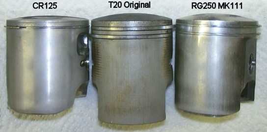
Three well-used pistons
Back to top
10) Carburettors
What carbs to use? Well obviously the originals aren't much use and what you use depends upon what state of tune you are running and whether you want top end speed (bigger diameters) or faster pick up (smaller diameters). I am running Fahron tuned barrels on one engine and Stan Stephens tuned barrels on the other. Both will be running on 30mm Mikunis.
There is only ONE place to go for your carbs and related stuff - Allens Performance. Not only do they sell carbs, cables, twin throttle twist-grips and manifolds, they even jet up the carbs for your engine based on their years of experience! They don't have Email at present though, so write or phone.
(Please mention www.t20suzuki.com if you contact them)
They look the business!
Allens supply the carbs 'ready jetted' but obviously every engine is different and there is no such thing as 'correct jets' - even the weather makes a difference with two strokes!
Allens supplied the carbs 'on the rich side' as that way you are not going to hole a piston or seize up. It then is up to you to get it right. This is how they came:
| Main jet |
230 |
| Pilot jet |
60 |
| Needle |
6F9 |
| Needle jet |
159.0-2 |
| Slides |
2.5 |
| Air Jet |
2.0 |
You can read how it ran on these settings in my 'Track Testing' section. However I moved the main jet size downwards and finished the season on a 210 size. This is still a tiny bit rich and I will alternate between 200's and 210's next year depending on conditions.
I changed the needle jets down from 159.02 to 159.00 and this helped the engine pick-up quicker from about 7000rpm onwards. (If you have the time it will pick up from 6000rpm, but you won't win many races that way!). This is how it finished the season. However, there is still work to do as when I changed the needle jets, it became harder to get it running from a standstill. The CRMC who I race with have all races start with the traditional push start, and although the bike always fires up immediately with a brief push, the engine struggles to 'get off the pilot jets' and rev up to the usable power range. This is costing me valuable time in races. I richened up the pilot adjuster screw which helped, but I think I need bigger pilot jets - I will try some 70's next season.
For clutch start races, the present setting is fine.
Carb Mountings
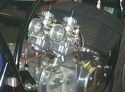
I have been asked how the carbs are mounted. Below is a picture of my Fahron barrels and the mounting method used. An Aluminium plate is bolted onto the barrel with two countersunk screws, and then manifolds (from Allen's) bolt to the plate. Your carbs are now rubber mounted and quick and easy to remove!
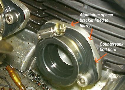
I'd just raced - ignore the mess!!
Back to top
11) Cables
The front and back brakes need specialist cables made up to fit. Some local bike shops can modify existing cables, or even make them up, but without a doubt, THE experts in the field are Venhill Engineering. I couldn't get the cables made until the bike was nearly complete, and of course, then it was rush to get them done in time! Venhill were SO helpful. I sent them an old back brake cable ("make the same but 3 inch longer") and a GT750 front brake cable ("make the same but 8 inches shorter"). However, the specialist cable maker was on his summer holidays, they were extremely busy, and I was desperate to get them made! Venhill couldn't have been more helpful though. I explained when I had to have them by, and to speed things up I collected them from the factory when they were done. It was a fantastic job, they fitted perfectly, and I made it to the test track. Thank you Venhill. They also agreed to a bit of sponsorship!!
They mail worldwide, and will make up any cable you want - so use them! (please mention www.t20suzuki.com if contacting them)

Back to top
12) Crankshaft
If your T20 is going to be tuned, the crankshaft needs to be in very good condition. The rods need to be strong to cope with racing stresses and 10,000 rpm plus. If you tune the rest of the motor and neglect the crankshaft you are asking for troubles....
The main modification is whether or not to convert your three bearing crank to a four bearing one. I have listened to many different viewpoints on this topic, and there are many racers out there using standard crankshafts. Personally, I am not convinced about this, particularly as I intend to 'thrash the nuts off' this bike and a four bearing crank is going to be much stronger. There are many different companies who can do the necessary work, most with proven race records. I sent my crank off to Ian Ambler. He has been highly recommended and as he says about his work, "I think my best achievement was 3 of my cranks in the first 5 one year at the Manx" - Not bad!
However, when Ian received my crank it was bad news.... The crank is pressed together, and if the fit is not really tight, you can't use it for racing (Mine was also somewhat rusty). I recieved the following Email from Ian:
| |
Adrian o Adrian.
What ever is that you sent me? I think it must be one of the worst cranks I've seen. Sorry about being so blunt.
You are going to spend a lot of money to do your crank right, this does not justify your money.
I will not rob folk, plus I like to see a good finished job.
Have you got or can you get a better crank please.
Sorry again Ian Ambler.
|
Oh Dear!
Now what? T20 cranks aren't exactly 'two a penny' are they? Well I posted up a plea for help on my site and Emailed everyone I knew. The response was great. I was given many leads to follow, and people asked around. I didn't get one, but I at least felt hopeful. Then along came my Knight in Shining Armour - Alan Ratcliffe. His old T20 is featured on my 'Your Bikes' page, and he is rebuilding a T20 at present from two old ones. On hearing of my predicament, he offered me his spare crank, cheap, and then mailed it straight to Ian Ambler for me. He also said to me not to send any money until it was pulled apart - that way I wouldn't have to pay anything if it was no use! What a helpful guy (as so many others out there have been - thanks a lot). I look forward to meeting Alan at a future race meeting or two (as my guest) not only because he is a top guy, but also because he used to be the mechanic for Carl Foggarty's dad when he raced! (Perhaps he'll bring his spanners....)
Well the crank was fine and Ian worked his magic on it. I now have a superb condition, 4 bearing, race ready crankshaft. Thanks once again to all who helped me achieve this.
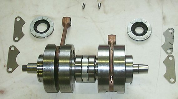
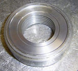
This is it - isn't it nice!
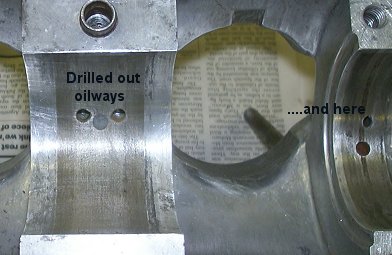
The two little 'pins' at the top of the picture have to be sunk into your bottom crankcasing and locate with small cut-outs in the edges of the two centre bearings. (You can see this in the picture below). This stops them spinning in the casing. A locating peg can also be seen on one of the outer bearings (like TZ ones?), the other bearing being left standard. All the old oilways feeding the original centre bearing have to be plugged - this I did by tapping the holes and putting in grub screws. I then finished this off with 'Liquid metal' (Araldite is fine) which is the grey stuff you can see in the picture below.
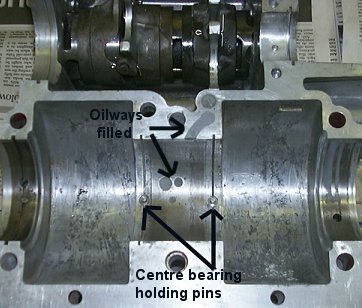
To ensure that your petroil mixture lubricates the centre seal, you need to drill oilways through the top casing from a place in-between each bearing and the seal, going up into the casing, and then you drill down the inner transfer ports, at an angle, hoping that your two drillings meet! I used a 4.5mm drill (as recommended by Ian Ambler) and had my heart in my mouth whilst drilling in case I messed it all up. Fortunately it all worked well....
To help the outer seals I did a similar process through the outer transfer ports. You can see the finished job in the pictures below....
| |
 |
|
The changing pressures in the crankcases, as the pistons move up and down, will ensure a constant supply of fresh petroil mix to the bearings and seals.
As you can see, I countersunk the openings to help the oilflow. I'm not sure if this helps, but it certainly looks nicer, if nothing else! |
| |
This shows the top casing from the inside. You can see the blocked old oilway, as well as the new ones that I have drilled. They are slightly oval shaped as I drilled straight up intothe casing with the 4.5mm drill bit, then used a 2mm bit to drill at an angle towards the transfer ports. The 2mm drill enlarged the sides slightly due to the angle I had it at, giving the shape that you can see here. |
|
 |
I was so nervous about doing all this correctly that I put the job off for about a month! I eventually had to do it though, as all the other work was done, and so I went ahead and did my best. It was easier than I anticipated, although it was fiddly. So don't put it off for as long as I did. However, remember the old carpenters saying "measure twice, cut once!" - I measured it all up about twenty times!!
Update 2005
One thing I didn't mention above is oilflow in the gearbox and clutch. In the original T20, the oil flow is rather unusual in that the gearbox and clutch have seperate, but linked, oil reservoirs - hence the two seperate sump plugs. When the engine is running, the oil flows from the gearbox through to the crankshaft centre bearing. This then exits into the clutch casing. As the level in the clutch casing rises, it is thrown up by the spinning clutch, collected by the oil reservoir cup (mounted on the top crankcasing behind the clutch) and this feeds it back to the gearbox. In this way the oil is constantly circulated round the engine.
However, by fitting the 4 bearing crank, you stop the flow through the centre bearing so that the clutch casing and gearbox are no longer linked.
It is therefore necessary to drill some nice big holes through the crankcasing wall, just by the gear lever shaft, so that the oil can flow freely between the gearbox and the clutch. This means that the levels in both halves stay the same.
Crank Life 
A crank should last you for a whole racing season. Most crank builders recommend a rebuild at between 750 and 1000 miles, although I have known some people use a crank for three times this amount!
I used my original Ambler crank for my first season's racing (5 meetings at the end of 2002) and for the whole of the 2003 season.
Being short of cash, I decided to keep using it for the 2004 season too, but it didn't work out that well......
At the first meeting of the 2004 season my left hand main bearing let go in the third race. The cage collapsed and this pushed out the LH oilseal, as well as sending loads of bits of bearing through the transfer ports into my cylinder. As if this wasn't enough to contend with, air was sucked in due to the oilseal being pushed out and this overheated the engine, melting the front of BOTH pistons! All this happened in about 3 seconds whilst I was leading the race.
As you can see, using a crank for too long 'to save a bit of money' is NOT a good idea. I've certainly learnt my lesson!
Crank Rebuilding
After blowing my engine up, I had to get the crank redone. Ian Ambler is of course happy to do this for you, but I instead asked Lea Gourlay to do mine. Lea, not only offered to do it for me, but he took my whole bottom end away with him at the meeting where I blew it up, and delivered the whole lot back, built up and ready to race, in time for my next meeting. Lea did a very good job, and at an excellent price too.
Lea now does all of my crank work (and team Spencer's too - see my 'T200 racing' page) and he can not only rebuild cranks for you, but can also convert them from 3 to 4 bearing too.
Feel free to contact Lea for any work you want doing - but don't forget to mention www.t20suzuki.com if you do!
Back to top
13) Fitting a TZ spec Yamaha crank into T20 cases
The T20 crank is a remarkably strong thing considering it is from a 40 year old road bike. The four bearing conversion is a must for the serious racer and works well, but what if you want even more revs and power? If you try to rev the t20 crank up to 12000rpm and beyond it twists and/or breaks. The interference fits are just too loose to cope with that amount of abuse. Also, the main beaings can fall apart after only a few hundred miles. I have had both of these problems with my cranks. The answer is to fit a TZ crank into your bike! This is something I'd heard of and fancied doing. I chatted to Lea Gourlay about it and we decided to go for it. Here is what we did....
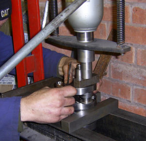
i) Initial preparation of the crankcases
The T20 main bearings and seals have an external diameter of 55mm, whereas Yamaha crankshafts have a corresponding diameter of 62mm. So, if you want to use TZ bearings, you need to line bore your casings to a new diameter of 62mm. This is a BIG increase (7mm) and it was with some trepidation that I did this. I dug out a badly corroded, spare set of casings and decided to us those. If it worked, fine, but if I trashed them, at least it was my worst casings cosmetically! I cleaned them up and took them, and a TZ main bearing, to B. J. Ashpole Engineering in Bishop's Stortford. This is an excellent company, who may not be the cheapest, but their work is absolutely first class. Ashpoles discussed the job with me in depth, but this led to the first problem - what interference fit did I want between the bearing and the casings?
I'd discussed this with Lea and he thought 3 thou would be about right. However, everyone I spoke to had a different value in mind. Ashpoles measured up my casings and an old bearing and told me that the present interference was only 9/10ths of a thou'! (0.0009 inch). They recommended a 1 thou' interference, Lea said 3 thou', so I split the difference and asked for 2! You can see Ashpole's work below:
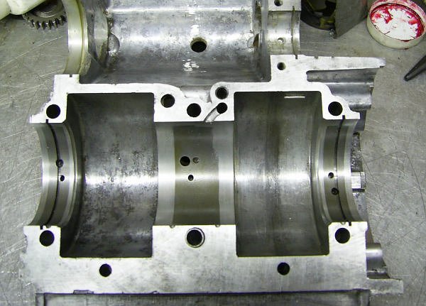
A nice finish. |
|
Plenty of 'meat' left. |
|
If you look carefully at the left hand picture you can see that the centre bearing steel insert has all but disappeared on one corner. This won't be a problem though as many bikes (eg the TZ) don't use steel liners at all. I was actually amazed how deep these steel liners were. They were still at least 2-3mm thick in most places - perhaps more. Ashpoles told me that it was a pig of a job to do. The boring tool cuts the aluminium to a slightly different diameter than it does the steel liner and that this was hard to minimize. My interference was probably 'just over 2 thou' in places apparently. One thing's for sure, you have to bang the bearings into place, and then struggle to pull them back out again. Bearing chatter is a problem with these engines, but the tightness of the interference should stop or minimize this. That was the preparation done, next job was the crank...
ii) The crankshaft
The first problem is getting hold of a good crank. The TZ 250 and 350 used the same crank so either will do. However, TZ cranks are getting very rare and expensive. The centre flywheels are also prone to cracking, between the crankpin opening and the centre shaft. Lea recently took apart three TZ cranks for a customer and two were cracked and the other one was too loose to use! There is a better alternative though and that is to use an air-cooled RD 250 crankshaft. These are the same dimensions as the TZ crank other than the centre shaft which is 2mm narrower - ie 30mm instead of 32mm. This 2mm difference gives the flywheel more strength between the crankpin opening and the centre and so prevents cracking. Lea now uses RD cranks almost exclusively when he needs to find or replace a TZ crank. You can use the TZ outer flywheels, with the two inner RD ones if you want.
There is though another slight problem - the ignition rotor fitting is different on the TZ/T20 to the later RD ones. The old points-ignition RD crank has the same rotor taper as the TZ one and the T20 rotor fits this too (with a little modification). So the early RD cranks - models A,B,C,D,DX - or an original TZ crank are the ones you want. The electronic ignition 'E' model has a very different end as you can see in the picture.
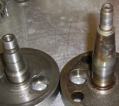 The 'DX' crank is on the left, the 'E' one on the right.
You can use the later model 'E' crank, but you will have to modify the end shown above. This is certainly do-able, but would possibly involve rehardening the rotor shaft afterwards. There is an advantage in using the later crank though as you'll see below - so it may be worth your time doing it.
So why use a later crank? The simple answer is balance... and lead! There are two ways to balance a crank - add weight or remove it. This involves either drilling holes and/or adding lead. In the TZ and later RD cranks, the solution used was to drill holes either side of the crankpin to balance the rod weight. Earlier RD models used a lead plug opposite to the crankpin. The lead solution is fine but there is a vague possibility that it could work loose at the revs we'll be using on the racetrack. You can avoid this (negligible?) risk by using a later RD crank, but you'll have a harder job making it fit the rotor. The choice is yours!
One way of reducing this risk is to drill through the flywheel, from the outside diameter, into the lead weight. You then tap the hole and fit a bolt that gives the lead a mechanical fixing. Then weld up the bolt head to the crank flywheel and grind it back so it becomes almost invisible. This probably isn't necessary, but it is worth considering.
Lea had a different solution for my bike. He wanted to use an RD 'E' crank to avoid the lead weight problem, but intended to use an RD 'DX' flywheel on the timing side. These are the two flywheels pictured above - the 'E' one that we discarded, and the 'DX' one that we did use. This left us with one leaded 'DX' flywheel. Lea was reluctant to use this as it was though, as he wanted this crank to be absolutely 'top notch'. The solution he used was quite ingenious. He knocked out the leaded weight and then turned down a steel plug so that it was an interference fit in the lead plug space. He pressed this into place, welded it in, and then turned it down in his lathe so that it was a perfect fit. This was then lined up in a milling machine with the 'E' flywheel and the balancing holes milled into it to exactly match the 'E' crank. I now had 4 matched and balanced 'E' flywheels, with the correct TZ rotor fitting!
|
The next job was to assemble the crank. The centre flywheels, bearings and seal are assembled first. We had a pattern labyrinth seal (rather than a genuine TZ one) and this was fine, but hadn't got slots in it around its outer edge. I wanted these, so that there would be a better flow of petroil mix around the centre bearings. You can see the outer edge on the picture opposite. The bearing outer races press hard up against this edge. I have drilled holes in my casings, from the transfer ports through to the bearing/seal joint, to allow petroil flow to the bearings. This was essential with the t20 crank (see the crank section above) but seemed good practise for this crank too. We quickly milled six 4mm wide slots on each side of the seal and then Lea was ready to assemble the crank.
|
|
The labyrinth seal |
|
|
One other advantage of the Yamaha crank is that the centre flywheels are manufactured with grooves in so that it is impossible to get them lined up wrongly. With the t20 crank you have to line up the flywheels whilst pressing it together. This then needs to be rechecked and adjusted continually. With the Yamaha crank, you put the bearings and seal in place, then press the two halves together in a press - done! It was interesting that about 7 tons of force was needed to push the Yamaha flywheels together. T20 cranks very rarely need more than 2 tons, and are usually nearer to the 1 ton figure! This is why T20 cranks can twist under high revs, but TZ ones don't.
|
|
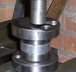
Pressing together |
|
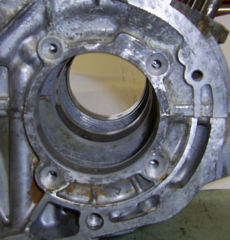
We then placed the inner flywheels into my cases to see what it looked like and to check the fit:
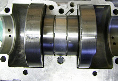 Doesn't it fit well! You can see the milled slots in the Lab seal too.
The next job was to fit the rods and the outer flywheels. We used TZ rods in the crank, although you can use the 'ordinary' RD ones if you want. The RD and TZ ones are the same dimensions, but the TZ rod is stronger, better made, has two oil holes in the small end eye AND has a much better big end bearing. The TZ crankpin is also solid, whereas the RD ones are hollow. The TZ rods are more than double the price of the RD ones, but to my mind, well worth it. (N.B. If you want a pair of TZ rods, get in touch as I can do you a pair for a good price.)
Lea put each crank pin in his lathe and added to the radius on the end of each with an oilstone. The chamfer on the pins is not always as good as it should be and this little bit of smoothing off helps the crankpin line itself up and locate better when being pressed together.
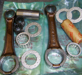
TZ con-rod kit |
|
Pressing it all together |
|
It was interesting to see the forces needed to push it together. Both sides needed forces of over 4 tons to push it all together. A T20 crank rarely needs two tons and are often not much above 1 ton. This makes the TZ crank so much stronger than the T20 one and allows for sustained high revs on the racetrack.
After pressing it all together, there is still a little alignment to do. It is essential that a crank is correctly aligned. The crank is rested on its centre bearings on a 'V' block and slowly rotated. A dial guage is run on the crank where the outer bearing will fit and the 'run-out' checked. In an ideal world, this would be zero but you are looking for a figure as low as possible. After Lea had finished 'adjusting' the crank (with a large copper hammer!) the run-out was down to about 1 thousandth of an inch from centre on both sides of the crank (less on one side!). You'd be very hard pushed to ever get a T20 crank to run that true. This helps reduce vibrations and increases crank life.
Lea then heated the outer bearings up to 110°C (with a bearing heater) and slid them onto the crank. We then placed the crank into the lower crankcase and it fitted beautifully. It really looked as if the crank had been made for those cases. The crank was slightly off centre though and so we removed the primary side bearing, fitted a thin shim and refitted the bearing. Perfect!
The crank was now done! There was still work to do with the cases though,and this is covered in the section below.
iii) Fitting the crankshaft
The completed crank dropped straight into the cases - it is amazing how well it fits - but some work was still needed. The first job was to cut small grooves in the casing to locate the main bearing locating pegs. You can see the two centre bearing pegs on the picture above of the centre flywheels. The crank was lined up centrally in the bottom case (note this point - 'lined up in the bottom case' - as it caused a problem later on...) and the bearings rotated until the locating pegs touched the front of the bottom casing. The cases were marked up and a tiny grinding tool was used to cut a locating hole for each bearing. The bearings were then rotated until the pegs located.
The next job is to cut bearing circlip grooves in the bottom crankcase, so that the locating circlips can hold the crank in place and prevent sidewards movement. When the casings were line bored, the original grooves were bored out, so we had a clean face to work with. The crank was carefully centralised in the bottom casing again, and the cases marked up where the grooves had to be cut. This is a tricky job, as all you can do is mark it up, remove the crank and cut the grooves. You can't get the grooves 'exactly' right as you have no base line to work with, and after measuring and marking up, you have to remove the crank and mount the casing on the milling machine. The best you can do is cut one, fit the crank and circlip, mark up the other side and then cut that.
Lea has made up an ingenious tool to help cut these grooves and he succesfully cut them both on his milling machine. If you get the grooves slightly too far apart you can shim one of the bearings to move it out a little. If you put them too close together... I have no idea what you can do!!
The photograph below shows the two grooves and the four bearing 'peg' locating holes.
 Two circlip grooves and four peg locating holes
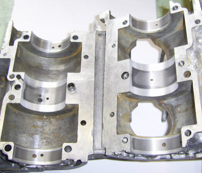
The alert ones amongst you will have noticed that the original '3-bearing crank' oilways haven't yet been filled up on this picture. If you are doing this job with standard casings, don't forget to block the oilways with 'plastic metal' and also to drill through the casing, by the gear selector shaft, joining the clutch and gearbox sections. This is covered in full in Section 12 above.
We had already fitted the top casing several times before cutting the circlip grooves, so we knew that everything was fine. All we had to do now was bolt it all together for a final check....
Problem time!
The TZ crank is a tight fit, but as said above, it fitted nicely. We had fitted the top casing a few times to check it was OK, and we'd even bolted the casings up to check, so nothing could go wrong now could it...?
The circlips were placed in the grooves, the bearings rotated to line up the pegs and the crank was fitted in the bottom casing. It was centralised nicely and then we fitted the top casing and bolted everything up. Nice! Unfortunately though, the crank no longer turned and looking at it through the top casing it was clearly off centre!! What on earth had gone wrong?
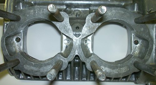
We tried reshimming the main bearing (thinking we'd got it wrong) and this centralised the crank in the top casing, but made it touch the side of the bottom one. AAARRGGHH! Now the problem become clear - the T20 cases are rubbish! The two halves were a matched pair but the crank flyweel spacings in the two cases didn't match! The actual castings had been made offset to each other. You can see what I mean in the picture below:
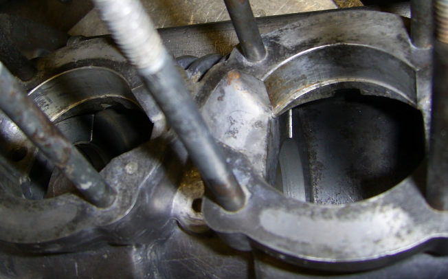 The offset is the same in both chambers, but can be seen more clearly in the RH one.
I wondered if it was a 'one off' problem but having looked carefully at all my spare sets of casings, it is clear that the casings were all manufactured like this. The casings were modified/improved at about engine number 50000 and the later ones are certainly better, but if you are modifying your engine, you have to be aware of this problem.
We'd spent a great deal of time and care lining the crank up centrally in the bottom casing and this had now caused us a big problem. The crank was only just touching the casing though, and as we'd already cut the circlip grooves and shimmed the crank up, the only way forwards was to modify the casings. It is essential that the rods are central with the cylinders and as we'd now lined this up correctly, it was the bottom casing that was causing the problem.
The bottom casing was mounted back on the milling machine and Lea made up a special tool to 'face-up' the two offending surfaces. We only had to remove a small amount of Aluminium - 10 thou' at the most - and this gave a suffiently big clearance. After cleaning up all the swarf, the crank was refitted, the cases bolted up and the crank span freely - Job done!
iv) Finishing off
Although I now had a new crank fitted, we still had work to do. I had to drill oilways in the casings and block up the old oilways as described in section 12. Also we didn't have any crank seals, the ignition rotor was 5mm further out than it should be, and the TZ primary gear is very different to the T20 one!
The first job I did was to drill out the cases to aid lubrication to the main bearings.
| The picture here shows the lubrication oilways that I drilled in the casings. I fitted the crank into the top casing and marked where the bearing/seal join was on each side. I then removed the crank and fitted a main bearing into each position and scribed a mark to show where this join was. You can see the scribe marks clearly. I then drilled holes from the centre line here, that I intended to emerge in the edge of the inner transfer ports. You have to do this at an angle and it is hard to line up. You could spend ages lining it all up on a jig, but as position in the transfer port isn't critical I did it all 'by eye'. I used a 1.5mm drill and started to drill down from my scribe lines. I then turned the cases over, and drilled down from the transfer port in an attempt to make the two drill holes line up. This actually works surprisingly well, but take your time and do it in small stages. Once I'd broken through the casing and the holes met up, I was ready to use a bigger drill. I drilled through with a 4mm drill and this helped clean up the slight mismatch where the two pilot holes were slightly out of line. I added a small chamfer with a big drill, and the oilways were done. If you look back up to the earlier photo of the labyrinth seal in position, you can see how the holes I had just drilled line up nicely with the bearing/seal joint. The slots we milled in the labyrinth seal outer rim allow petroil mix to move through the bearings and up or down the transfer ports. This has to help lubricate the bearings. I repeated this in the outer transfers to help oil the outer main bearings.
|
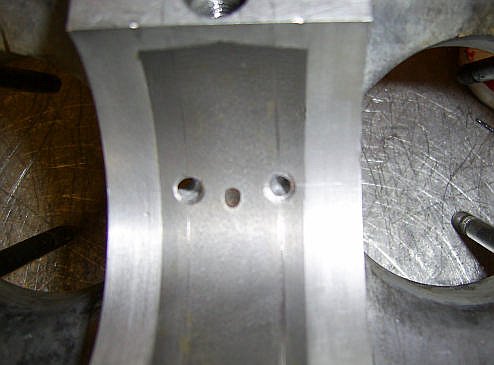 |
Are these drillings necessary? No idea, but it sure makes sense to me.
I'll write up how we solved the final problems when I have time, although in brief:
New primary gear - made by Nova Racing
Ignition rotor - modified by Rex Caunt Racing
Crank seals - new crank seal holders made by Lea Gourlay

I'll get on to it asap!
Back to top
14) Gearbox
i) The gears
If you have read my 'Fun I Had' section, you will know that T20 gearboxes aren't the strongest of things. However, there are many T20s out there racing with the standard gearbox, so maybe it's just me..? There are three main options regarding gearboxes for racing; standard 'box, high first gear, completely new close-ratio racing 'box.
The standard gearbox has quite good ratios for racing, although the standard first gear is very low. It is hard to find parts in good condition, and if your gearbox has seen a lot of service already, with worn dogs and corresponding locating holes, you are in for a lot of 'missed gears' or even it jumping out of gear under load. I was given a tip though by a T20 owner that I met at a race meeting - He said to undercut all the sides of the dogs and locating holes so that when the gears engaged, the contact surfaces would be angled and pull both the gears together. The gears are originally cut like this, but wear with use.
|
 |
|
My gearbox was actually in excellent condition with only first and second being noticeably worn. However, these are the ones that will keep jumping out under load. I found a local company that would accurately undercut the dogs on my second gear - they did this for only �10.00 - an excellent deal. You can see here one of the three surfaces that they ground up for me. |
The first gear, which is too low for racing anyway, I replaced with a brand new higher ratio gear. This can be done quite easily. All you do is replace the 36t gear with a 33t one! The cut angle is different so it allows for only one gear to be changed! Engineers out there will be telling me that this is impossible, but it is a common conversion, it works, and I've done it! These are manufactured in batches of 10 by Nova Racing. Martin Crooks is always prepared to order a new batch to be made up, if he gets sufficient orders (5 or 6). Through this site, we managed to get enough orders (I bought two - one for each engine) and this is now fitted and working.
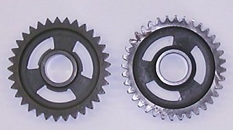
New one on the left
If money isn't a problem, then a complete brand new, close-ratio box is the option to go for. At present Nova have none in stock (I'm told) but would be prepared to make some up if they can get an order for about ten of them. Interested? Then please get in touch with me.
ii) Selector forks
Another problem is selector forks - these break, overheat, wear and bend. They are presently unobtainable new from any supplier anywhere in the world (as far as I know). My only set of forks have nearly all of the above problems and will have to undergo welding and be finished with 'stellite' before I am ready to build up the engine.
Update:
I wrote about the useless selector forks back in 2001, and a kind reader of this site, Alan Ratcliffe, sent me an almost brand new set of forks through the post! He is also the guy who supplied my crankshaft, when my original one turned out to be scrap. Thank you so much Alan - I really would not have made it to the track in 2002 without your kind help.
iii) Selector drum
As riders of old T20's will know, the early Suzuki's had a 'positive stop, neutral mechanism'. What this means in reality is that you can change straight up from 1st to 2nd gear, but when changing down from second you ALWAYS change into neutral first, then have to change down again to find first gear. This is superb on the road, and works well. However, it is not much fun on a racetrack. There are people racing Suzuki's with this in place, but I was determined to find a way of removing it.
The reason you can't change straight down, is the slot in the selector drum that is extended so that only a half change is possible. This slot has to be filled in, leaving behind a normal size notch, exactly the same size as all the others. See pictures below:
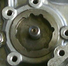
The standard drum |
|
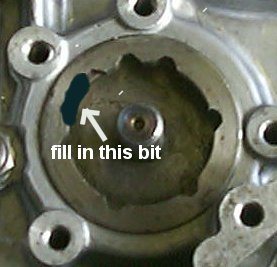
Modify the slot as shown |
|
I wondered about filling in the top notch so that I would have six equidistant notches set around the drum. This however is unnecessary - I left it in place and haven't noticed any problems. However, please be VERY CAREFUL if doing this modification. The casting is a High Carbon steel and welding it up is very difficult. It is also imposssible to 'file up' afterwards as it becomes too hard to file or even machine. Only grinding works! I know of people who have had their one and only selector drum totally ruined whilst trying to get this done - YOU HAVE BEEN WARNED! I had the slot welded up to exactly the correct shape by a skilled welder. I have since heard that some people make up a filling piece and then solder or braze it into position. This seems the least risky option if you can find a toolmaker to do the job for you.
You can get selector drums that don't need modifying - Suzuki didn't have the 'positive-stop' mechanism on all of its bikes. I'm not sure when it changed (or if it was just for the TC250 model) but I have recently aquired some engine spares from a late engine - Engine No 57*** - and this doesn't have the cutaway. You could try and find one of these.
Back to top
15) Clutch and Primary Drive
By the time I got to getting the clutch sorted out I had run out of money! So, there was only one viable option - all standard. The clutch housing originally on the bike had an outer segment on it broken off. I had another clutch, but it had spent twenty years or so rusting away - this then was the one I used. I had to prise the plates apart due to the rust and muck and then set about cleaning it all up. I couldn't afford new plates, but I did get a set of heavy duty clutch springs from Crooks Suzuki as these didn't cost much and are an essential modification.
On the track, this all worked absolutely fine. I use semi-synthetic SAE15-40 oil in the gearbox and the clutch drags when cold, but has never even hinted at slipping when warmed up. Despite using an old and worn clutch, I did the remainder of the 2002 season AND all of the 2003 season on those plates before replacing them. I replaced them eventually as I'd started slipping the clutch a bit to get me out of bends when the gearing wasn't quite right. At the end of 2003 there was a horrible smell of burnt clutch plates in the engine oil.....
Although dipping the clutch to get the revs up is acceptable now and again, this was becoming a habit due to the ridiculously narrow power band of my engine set-up. The Lea Gourlay tuned barrels that I used from 2004 onwards transformed my engine, giving me a much wider power band, and greatly reduced any need to dip the clutch.
Most of the racers I had met used straight cut primary drive gears. These were availiable (as is everthing!) from Crooks Suzuki, but at about �270 were out of the question. So, I raced the 2002 season on the standard helical cut gears. However, my crank man, Ian Ambler, had told me that using the standard gears tended to pull the crank sidewards and cause heavy wear on both it and the bearings. Also, the straight-cuts are said to be worth 3-4hp at the back wheel - definitely worth having!
Well at the top of my Christmas list was a set of straight-cut gears and Santa Claus duly delivered (well my wife actually - thank you so much). I fitted these for the start of the 2003 season and they had their first outing at Pembrey. I didn't manage to do a dyno run 'before and after' fitting them but the difference was clear. The engine was defintely noisier but also seemed to be more responsive and generally 'looser'. Hard to describe really, but it was certainly better.
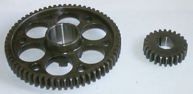
Don't they look superb!
The tendency of standard primary gears to apply sidewards forces on the crank is of course removed with the use of straight-cut gears. As my engine became further developed, gaining more and more power, this sidewards force would have become more of a problem. It is hard to say how much of a problem, but Spen's T200 Suzuki (see 'T200 Racing' page) really suffered from this problem after Lea Gourlay had tuned it (Incidentally, it must be the fastest classic 200cc bike ever built now!). On a couple of occasions the crank tried to push the main bearings out of the casing and the bike suffered from broken main bearings and broken fixing circlips. Spen either had to buy some straight-cut primary gears, or get his rider to 'slow down a bit'! Nova Racing, who made mine, don't manufacture straight cut primary gears for the T200 (although they would if you bought 5 sets), but Spen's rider Terry is an engineer by trade whose company has contracts with a gear manufacturer. Terry's employers - Penny Hydraulics - sponsored Terry by paying for a set of straight cuts to be made up as a one off. They did a beautiful job and helped (further) transform Spen's bike.
If you are going to race one of these little Suzuki's seriously, you really must buy some straight cut gears.
Back to top
16) Exhausts
There are two main options here in the UK if you want new exhausts, either Abcon exhausts or Swarbrick Racing ones. I couldn't afford any new ones, as I had 'over spent' somewhat, but fortunately, through an advert in my website 'Noticeboard', I managed to pick up a second hand pair of pipes. Ideal for those on a tight budget, as I now was.
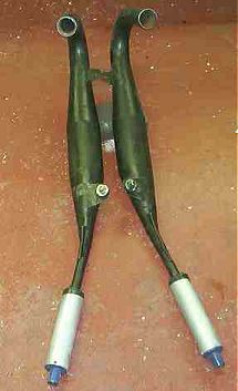
Abcon Exhausts
|
|
I got these from Dave Brown (see his bike on my 'Your Bikes' page.
I was very pleased to have them, but then had to find a way to make them fit. The header pipe fitted the engine perfecty, and the shape of the pipe was right, but the mounting mechanism was a rubber bush type system that lined up with absolutely nothing on my frame. I could either add a mounting bracket to the frame, or modify the pipe so that they bolted to existing bracketry on my frame. As I had heavy duty arc-welding equipment avaliable in my garage, but no gas welding equipment, the choice was easy - add a mounting to the frame! You can see the bracket I used in the second photograph. |
|
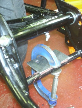
That is one substantial plate!
|
|
The picture on the right shows everthing lined up. The pipes are held in position with elasticated 'bungee' straps and are bolted to the mounting plate. The green scouring pad (for cleaning aluminium surfaces) is keeping the pipes just the right distance from the frame. The rubber mounting brackets are car exhaust parts - Austin Mini I think. They are avaliable from any good car parts shop. Incidentally, these don't last for ever - change them every season. One of mine fell apart at Croft and my exhaust nearly fell off - I lockwired it up to last the meeting.
Everything was now in position ready to tack and weld up. |
|
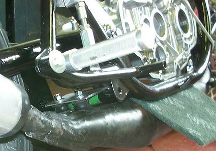 |
Changes for the 2006 Season
I used these pipes succesfully for three seasons racing, but after tuning up my engine, Lea Gourlay wanted to try something better. The pipes were too restrictive, he felt, and were far too quiet (That's news to my neighbours!). He wanted to fit TZ Yamaha ones. The TZ250'G' model has the same bore and stroke as my bike, so that was what I needed. Swarbricks will make you T20 pipes to TZ250'G' spec, but they aren't cheap. I managed to get some damaged TZ ones on Ebay at a very good price and Lea modified them to make them fit. The header pipes on the TZ ones are at totally the wrong angle, so you need to change this WITHOUT changing the overall pipe or header length. We also changed the mounting system so they now bolt on to the bracket that you can see in the photo above, just below the brake lever, making them much easier to get on and off. This was the bracket I'd planned on using before I got the original pipes.
Did it make a difference? It sure did. It seemed much more powerful and now wanted to rev on up to 12000rpm (and beyond!). You can change the lengths to bring down the peak rpm, but unlike before, my engine now made peak power at just over 11000rpm but would rev right past 12000 if you needed to hold a gear for a little longer. We set it up on a dyno, but unfortunately I had a dodgy ignition coil that spoilt the session, although we did get a reading of 51 bhp inbetween all the coughs and misfires. After replacing the coils and jetting the bike correctly I'm pretty sure that the bike was now producing around 54-55bhp. This is how I raced it for the 2006 season and it was an absolute dream to ride. My only concern was the extra power and revs would rip the crank apart. I tried to keep it below 12000rpm at all times and avoided going much above 11500, but what I clearly needed for 2007 was a far better crank. This was why we decided to fit the TZ spec crank - detailed in section 13 above.
Back to top
17) Ignition System
I have spent a lot of time doing research for this part of my website, and am very pleased to report that not only have I found the supplier of THE best ignition system that there is for a T20 race bike, but also that the company involved have kindly offered me some sponsorship!
I met the TZ owners club at the Stafford Show and was told that Rex Caunt Racing were the experts when it came to TZ ignition systems. I got in touch with Rex and he told me that not only does he make and repair TZ stuff, he has also developed and stocks a set-up specifically made for the T20. This is the system used very succesfully by Kevin Strowger (whose bike can be seen on my 'Your Bikes' page).
There will be a pic of the T20 set-up here shortly, but in the meantime you can see below the system that Rex sells for the TZ350:
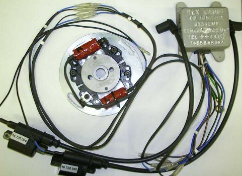
This is a TZ350 Mark 111 set-up
|
The T20 set up has a modified rotor (shown below) that sits out a little further than the original.
 |
|
You can clearly see how the rotor sits out a little on the picture on the left. The other picture shows the inside face. This then rotates inside a modified TZ system (as shown in picture above) that bolts directly into the T20 crankcases. A very nice system indeed!
|
|
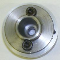 |
 |
|
The bottom oilseal retainer piece is replaced with Rex's own thicker Aluminium one as shown here. The ignition system backing plate screws into this bracket, as well as the casing at the top, in order to further hold it steady. As you can see, the whole set up is well designed, and fits directly onto your T20.
|
However, it isn't just having a spark that makes a race bike competitive, it is having the appropriate ignition setting across the whole rev range. Rex's system has an electronic advance and retard built in, which gives your bike far more pulling power and tractability throughout the rev range:-
|
Engine revs |
|
Timing advance |
|
Engine revs |
|
Timing advance |
|
1000rpm
2000rpm
3000rpm
4000rpm
5000rpm
6000rpm |
|
26.0 degree
27.0 degree
25.5 degree
23.5 degree
22.0 degree
21.5 degree |
|
7000rpm
8000rpm
9000rpm
10000rpm
11000rpm
12000rpm |
|
20.0 degree
18.0 degree
15.5 degree
13.5 degree
11.5 degree
9.5 degree |
"But the advance and retard goes the wrong way!?" you say. (Well one or two of you have.) I queried this with Rex, as I also thought that engines were supposed to advance the timing as the revs progressed, not retard it.
Rex replied:
|
"Since the early '80s much two stroke research has focused on electronics. We have seen the introduction of power valves to control the point of opening of the exhaust port. Initially this was performed by mechanical means, then designers found that to enhance the power band a control by an electric motor, itself controlled by a computer gave far more scope for power increases, especially in the midrange, just where you need to accelerate from a corner.
Part of the search for midrange power focused on the ignition timing. It was found that beneath the power band created by the tuned exhaust system, more ignition advance could be given than could be tolerated at the peak horsepower rpm. A study of a MK 3 TZ350 curve will illustrate this. (Diagram to follow)
Then it was found that a further retard of the spark timing caused the exhaust pipe to run hotter, which affected the speed of the sound wave in the pipe.
The net result was the pipe stayed in tune longer after peak horsepower by keeping the torque up.
We have found that retarding a fixed timing setup, by say 2-3 degrees, will give more power after peak horsepower, but there will be a drop in power on the climb up to peak horsepower. There a tailored ignition curve can give gains over the fixed timings we were used to in the early days of racing two-strokes. With limitations in engines by piston crown temperatures it pays to approach the design of the curve with care and dyno testing sometimes has to be verified with actual track testing. The same applies to other settings on the engine and the whole picture is usually a blend of art, science and experience, with failures on the way, such as holes in pistons!
Hopefully this will give a brief explanation of why the general two-stroke ignition curve differs from a four-stroke curve which normally has a rise in ignition advance with a rise in rpm. Further study is recommended by reading books on the subject such as "Basic Design of Two-Strokes" by Doctor Gordon Blair and " Two-Strokes Performance Tuning" by Alexander Graham Bell."
|
So there you are. Years of research and hard work summed up in on or two paragraphs, supplied totally free to all of you people out there....thanks Rex.
The total cost of the ignition system from Rex Caunt is �450, and as it is designed for the T20, has a proven track record, and comes complete with coils, tacho drive etc, I think that it is a very good deal. If you look at Rex's website on www.rexcauntracing.com you can see that he makes complete systems for all kinds of bikes from old Villiers singles and twins to Trials bikes, Motocrossers etc. Phone or Email him for individual requirements/discussions etc. (Don't forget to mention www.t20suzuki.com!)
Cheaper alternatives
The above system really is the way to go, but not everyone can afford the outlay at first. A correspondent of mine, Nick Johnson, used the standard points and alternator for his first season! However as he says -"I wouldn't use the points if I were you as they had to be reset before each race". Well, thats one way of doing it on the cheap - although I don't fancy all that fiddling around with points before each race! Nonetheless, I admire Nick for his determination to 'get out there' and have some fun one way or another. After all, thats what it is all about isn't it?
Nick now uses a standard road bike electronic ignition with battery, which he says easily lasts for a two day meeting. However, when you have bought your coils, battery and electronic set up, you haven't saved that much money really! Also there won't be much (any?) advance and retard built in so you will lose out on tractability. So go on, treat yourself and get the best set up there is - click on Rex's logo above!
Back to top
18) Petrol Tank
If you want a TR250 type replica petrol tank, there is only one place to go in the UK - Peter Keyte, of Custom Tank and Designs. If you want one though, order it early - he's a busy man and it can take months if he has lots on. I am amazed at the high quality and yet low price (�150) of these - order one now!
The tank is made to Peter's own design but is based on the TR250 original. It comes with a Monza type filler, holds 16 litres, and you need to specify what type of tap you are going to use. He recommends the Yamaha TZ one for a bike as thirsty as a tuned T20. The 16 litre version fitted to my bike is fine for short track circuits, but for the Manx GP you need a bigger version.
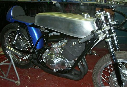 Contact Peter on 01386 554136. Alternately, send a deposit, say �25, with an order to him at: Unit 23, Pershore Trading Estate, Pershore, Worcestershire, WR10 2DD, England. (Please mention www.t20suzuki.com)
You can specify different design, capacity and cap, but talk to him first. Incidentally, he never advertises, doesn't have a computer or Email address, and has a backlog of work! He must be good.
You can see the one of the rubbers that the tank sits on at the back, on the frame rail. There is one of these either side. At the front, when bracing up the steering head, you need to put a tube (approx 8mm diameter) though the bracing so that it is perpendicular to the bike. On either end of this you put some rubber mounts and then the tank slips onto these with the 30mm diameter 'C' shaped holders that Peter fits to the tank. (I'll photograph it!) The tank MUST NOT touch the frame anywhere, or else it will fracture.
Back to top
19) Bodywork
Racing fairings, seats screens etc are readily availiable from many sources. I have bought a fairing from Crooks Suzuki as they really look the part in the original blue and silver colour scheme as can be seen below:
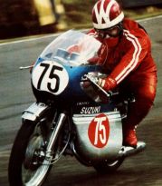
T250 in 1970
|
|
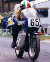
Martin Crooks in 1998
|
Crooks mail all over the world and new fairings in white are � 40 + VAT, metallic blue � 50 + VAT, screen � 25 + VAT. They also do seats for about �25 + VAT. (No VAT for overseas customers, I think....)
I have had much mail about fairing fittings - where do you get them from, how do you make them, etc. This was something that I was not looking forward to doing myself. However, I was given a head start by picking up an Andy Bacon modified frame (Abcon), with much of the work done for me! What a help this was.
In effect, you need to mount the fairing at five points, the front, the bottom rear (both sides) and the top rear (both sides). I will show you how mine is done, along with some others....
Front fitting
You need a tube of some kind welded to your headstock, horizontal and pointing forwards. You then have many options. Here you can see the Andy Bacon produced Tacho mount and fairing fitting on mine! This slides into the welded on tube (which has lock bolts to tighten around it).
In the end of this tube, you fit something that can mount to your fairing. If you have another tube that can slide in and out of the one you can see here, then your fairing is easy to adjust or remove. You can see below the bit I made (in silver) along with the holes I drilled in the wrong place (in white!)
|
|
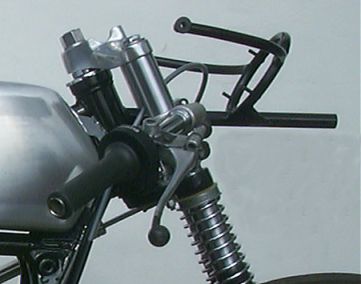
|
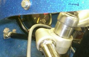
The silver tube slides easily in and out.
|
|
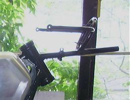
You can see the lock-bolt here
|
Top Rear fittings
There are many different ways of doing these, but they are all basically the same method - a bracket is made up that bolts to both the frame and fairing. Again, for easy removeability, I had a sliding tube on the end of the bracket, help on simply by an 'R' clip.
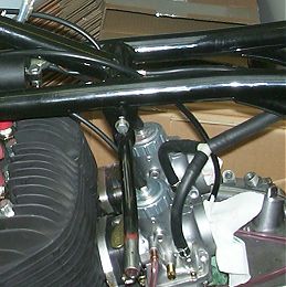
Here is the bracket, bolted to lugs on the frame..
|
|
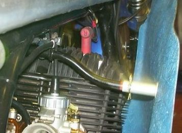
The silver 'end cap' bolts to the fairing.
|
For a very nice and neat solution, have a look at Kevin Strowger's bike in my 'Your Bikes' section. Very neat and tidy.....
Bottom Rear fittings
Here you just need a bracket either side of the bike, either welded or bolted on. You can clearly see mine in the picture below, along with the rubber spacer to help cut out vibration/cracking etc..
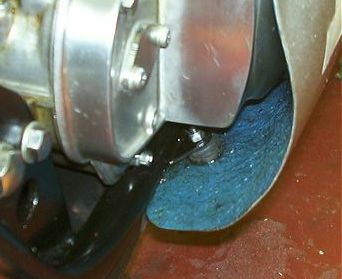
I hope that you have found this helpful, as I know that I would have done!
Back to top
20) Track testing
Test Session 1 |
August 21st |
On first starting, it sounded very rattly low down, like bad piston slap, but this cleared at higher revs. I will investigate this later, but it will have to do for now. I ordered a front tyre for testing at Mallory Park on the Wednesday, but the guy bought one that to my mind is too big by far (110/80 x 18) I had no choice, so had it fitted - I wasn't going to miss a practise session after 18 months work.....
I was so nervous when my testing session started, but I opened it up and off I went.
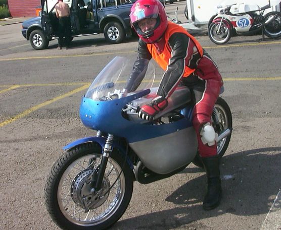
Nice novice's orange bib!
Out on the track and there was a truly awful misfire at midrange (I haven't got a tacho yet!) that you just can't seem to rev through - the mixture is obviously far too rich at this point. Opening and closing the throttle seemed to make no difference at all. As I was trying to carefully run it in, this was a pain. However, I knocked it down a gear to get past the problem and opened it up, the engine note changed to a wailing scream and the thing flew! Boy it was quick. So running it in carefully went out of the window and I thrashed it instead!!! It went very well indeed. Out of the hairpin and bus-stop though, the misfire was a pain. The gearing seemed good for Mallory, with it pulling pretty high rev's in top at the end of the start/finish straight.
Handling was OK, but out of the long fast sweeping Gerards bend it wallowed horribly. Putting the rear shocks two positions stiffer helped, but it was still not brilliant. However, elsewhere on the track it was really great. Under heavy braking the front forks were nearly bottoming, but as the brake works on both fork legs, there was no twist to worry about. I will be making up some 15mm spacers to help pre-load the springs and will try some thicker oil in the forks.
Update: I put thicker and thicker oil in and eventually setled on SAE40 engine oil that my mate uses in his Vincent engine. This does the trick nicely, and I haven't had to put spacers on the forks. I still may do this though.
The brakes bed in nicely and I was soon outbraking some triple disc'd bigger bikes into the hairpin! (woosey riders). After a while I was trying to ride smoothly and work out the best braking points, although as the brakes continually improved, this was difficult. I got faster and faster and really started to enjoy myself, however, after about 10 laps, coming out of the hairpin I really opened it up to try and overtake a Honda 600 I was next to, when the back slid out sidewards by about 40 degrees or more. Just as I was thinking "I hope this doesn't smash up too badly" I ran out of revs, the back gripped and I recovered and carried on - Phew! I pulled in after this to check the back tyre and was amazed to see the rear mudguard, crankcases, frame etc drenched in oil and petrol. I hadn't realised how much blow back there was from the carbs on an engine like this, and what with the misfire, it was a right mess. I now have to redo the rear mudguard so that all the shit thrown out of the carbs doesn't fly onto the tyre. However, the tyre was actually OK, my slide at the hairpin was due to me being over-exuberant with the throttle.......
On pulling in to the pits, my spanner man, Eric Blakely, commented "I thought you were going to go steady and bed it in!" Yes, I'd thought I was going to as well.... We checked the bike over, plugs, tyres etc and found about 5 or 6 nuts and bolts missing! The plugs were OK, a bit rich, but reasonable for a new engine. We quickly made up a new 'screen' for the rear end to help shield the tyre, and replaced or retightened nuts and bolts. I have now learnt why wiring up bolts is essential - three of the four bolts that held on the seat were missing!! I had run out of Nylock nuts towards the end of the rebuild, and thought it wouldn't matter too much at first...... How wrong I was. I will have to put Nylock nuts everywhere, and drill and wire all suspect bolts. (Even one or two loctite'd in ones, fell out later on!)
I tried lowering the pins to cure the misfire, and during the next session on the track it definitely helped, but didn't remove it (you could just about rev through it now though). I have work to do before next wednesday's test session at Mallory. I have been offered carb tuning advice from Rex Caunt, Dave Brown (who races a t20 very succesfully), and others. I will try smaller needle jets next week, and see what else I can do.
On my third and final test session, my confidence grew, and the speeds crept up. I thought I had my braking about sorted second time out, particularly at the hairpin, where I braked half way through the shadow of the big tree on the right hand side. Trying desperately to outbrake bigger bikes this session though, I completely cocked-up at the hairpin. I overshot my turn in point twice, and nearly went off on the next lap! It then struck me why - shadows move as the day progresses!!!! I was therefore braking a good few feet later than I had meant to - ho hum.... I continued to have great fun, and then round Gerards it suddenly felt like it was going to nip up. I yanked in the clutch, but it carried on, then stopped. I was very worried, but actually, I had just run out of petrol. Seems it only managed about 18mpg.
Well as you can see from the above, I was under-prepared, rushed, over-exuberant, too heavy handed with the throttle, and basically a complete novice at preparing a race bike for the track. But, you have to start somewhere. I will share all the things I do (good and bad) on this site, and perhaps help any other novices out there to a few shortcuts, in the way so many people have helped me.
Watch this space for details of test session number two..
Test Session 2 |
August 28th |
Last week I didn't have a rev counter, but this week I had been lent one by my friend Eric Blakely. It will hopefully give me a better idea of what is happening where. I changed the main jets from 230s to 220s to see if that improved things and went out for my first test session Out onto the track and it was running better at the top end but no better in the mid range. Having said that, from about 7000rpm on it picked up nicely, and then went like a rocket at 8000rpm up to about 10,500rpm. Handling was still suspect and round Gerards I could hardly hold on as the back bounced around and the front wobbled. I was lapping in around 67 seconds though, so it had potential. Back into the pits and as the main jet change had made no difference, it was time to change the needle jet. I went from 159.0-2 down to 0-0's. I also shifted the rear shocks from the hardest position to the middle one (having tried both hardest and softest already). Time to go out again and check it out.....
Now it really did fly - the jetting was much better. It had a slight misfire at 6000rpm, but then picked up cleanly all the way to 10,500! The handling was a little better and I really enjoyed myself out on the track. It was by no means perfect yet, but certainly well on the way and running well enough to compete at Lydden 3 days later. My laptime was improved by 4 seconds as I was now lapping Mallory in 63 seconds, which shows how much better it was. My main jets were still too big and I intended to drop a size for the third and final session, so in to the pits I went....
A quick check of the bike and the blow-back from the carbs had been massively reduced - another good sign. But oh dear - the back wheel wobbled from side to side and was VERY hot. The bearings had come loose in their housings and the wheel was moving from side to side. The brakeplate had been touching the wheel and bits of Aluminium were everywhere! I wondered if I had been resting my foot on the back brake lever without noticing it? Whatever, it had got very hot, which had helped the bearings move, which had caused damage to the brake hub. Oddly, the brakeplate was touching the wheel all the way round on the inside, but stopped doing this when it had cooled down. Apart from that, the steering head bearings had worked loose, as had the top yoke securing nut. This was the end of the days testing, I had no spare wheel, and Lydden was in three days time...Oh despair!
On the way home, with discussions about what to do, Eric Blakely suggested borrowing his T20 rear wheel. So, back to his house, strip the wheel off, and Lydden was back on...
Back to top
21) My First Race Meeting
We arrived at Lydden on the Friday night and set up camp. Final checks had been made, all we had to do was sign on, pass scrutineering in the morning, fit a transponder to the bike (for recording lap times and race position) and go! Before it got dark we walked round the track so that I could get familiar with it, and Eric passed on as many tips as he could. This really helped me a lot - an essential thing to do at a new venue.
Saturday came, scrutineering was no problem and then, at the appointed time I went out for a short practise. Wow - so exciting and the bike was running lovely. I had earlier changed the front fork oil for SAE40 engine oil, and this really helped settle the front down. The rear was behaving itself, and the engine was sound - Race on!
Race one
The 250cc twins (my class) race with the 350cc four strokes twins (almost all Honda K4s). There were 18 of us on the grid (sadly quite depleted due to the Classic Manx being on at the same time) and I was near the back as I was a novice.
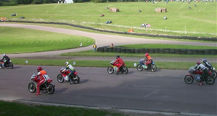
I'm on the far side of the grid
The race started with a push start, and although my bike always fires up immediately, the pilot jets are too weak and it doesn't pick up very quickly. I had a reasonable start though and then chased those ahead. I was determined to finish, not blow it up, take my time and learn the track, and improve in the next three races. I did well, made a few mistakes but finished in 13th place of those on the grid, but more importantly, 4th in the 250cc twin class - I had won a trophy in my first race!
Race two
I had done well last time out and my final lap had been my fastest, so race two should be better. I was determined to get third place this race, as I had been overtaken right at the end when I missed a gear on the last lap.
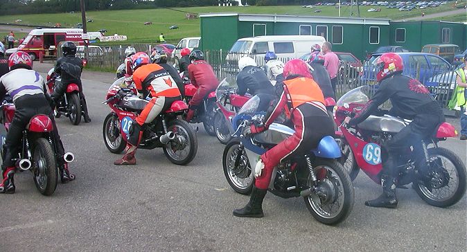
In the warm up-area before the race
I was much more confident this race, and lapped at a far more consistent pace. My fastest lap was just under a second better, but more importantly, all the laps were good. Disaster nearly struck at the hairpin though where at full tilt, and 8000rpm the back slid out sideways. Just like at Mallory though, it ran out of revs, straightened itself up and carried on - phew! Dixie Dean (Yamaha YDS5) who was just behind me only just missed me and ran wide onto the grass - sorry about that...
Dixie overtook me next lap though, and the race finished with me in 10th place overall, but third in the 250cc class - yippee! I was well chuffed. I had completed my first days racing with a third and fourth place, no accidents, no engine explosions, and a lot of positive praise and comments from other competitors and spectators alike - A good days work. Could I do better on Sunday?
....Bike problems....
We checked the bike over after the race and oh dear - the back wheel had messed up again (see Track Testing section - session 2). Not quite a disaster as the bearings were still in place, but the cause of the problem both here and at Mallory became clear - the brake plate was expanding due to the heat and became too big to fit inside the hub! I took a file to the plate (it will be in the lathe when I get home) and filed a lot of metal away all the way around. This gave me more clearance and the problem did not arise again. However, I hadn't had time to drill loads of air vents in it before finishing the bike, whereas every other one I have seen looks like a Swiss cheese. It was partly this causing the problem, and partly due to me using the back brake too hard when riding. Being an ex motocrosser, I find it hard to leave the rear brake alone - it is something to work on. As the front brake bed in though, there was less and less need for me to keep stomping on the rear.
A bit of engineering on the brake plate and a little work on my riding style and there will hopefully, be no more problems with it.
Race three - Sunday
The mixture was still too rich so I had reduced the main jet size to 210 before the race. Would it help? I had an OK start and then really went for it. I was determined to beat yesterdays performance. I was braking very hard into the bends and had the front wheel hopping along the tarmac at times. I was powering it on earlier (except at the hairpin which still scared me a little) and was definitely going faster. I saw Dixie Dean up ahead on his YDS5 and caught him up and overtook him! WOW - I was in second place.
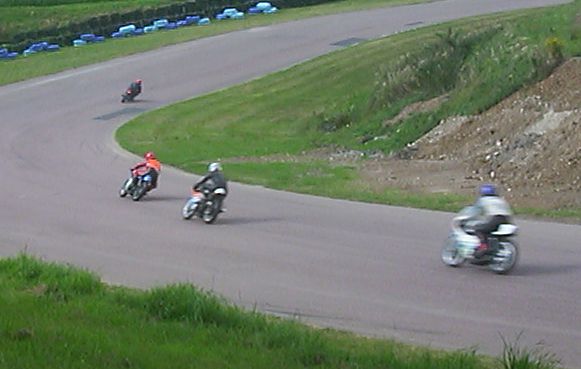
Me going into Pilgrims, Dixie Dean two places behind
I was really steaming along until I missed a gear, hit a box of neutrals and was overtaken by two 350cc Hondas - damn. I caught them both up though, overtook one and the other threw its chain off just as I was going to have him. I ended the race second in the 250cc class with my best lap time over 1.25 seconds less than Saturdays best. This was a trophy race, so I had another trophy to take home - for second place this time though. The bike had stopped smoking, so the mixture was better, but it was still a little too rich. I need to go to 200 main jets, but left it as it was for the final race.
Race four
I was nervous about this race. I had done so well so far, and hadn't fallen off or blown anything up. I really didn't want do anything stupid and ruin my weekend. Nonetheless, the race got going and I went well. I had a poor start (must sort out the pilot jets) and saw Dixie on his Yamaha a good distance ahead. I tried to catch him, but couldn't so settled for a safe finish. Again I missed a gear early on and a 350 Honda came past. I was annoyed and went after him. We had a real good battle, swapping the lead from corner to corner. I was outbraking him in two places, but he had the low down 'grunt' out of the bends to just get away. I passed him again on the final lap and made it stick - excellent! I hadn't improved my lap time on last race, but with another third in class, a solid engine, a good race, no crashes or smashes, I was very satisfied.
I had had an excellent first weekend racing; loved the friendliness of all at the CRMC, and went home with two trophies, some experience, and a big smile. See you all at Cadwell in October....
So who came first?
In the picture below you can see a very happy man from Rochdale - Dave Brown. Not only did he win all four races that I was in, but also won �120 in the 250cc Championship round for another first place! (I'm not allowed to enter this race as I am only a novice). His T20 absolutely flies, AND Dave knows how to ride - he was lapping Lydden consistently two seconds faster than I could manage in my best lap of the weekend!
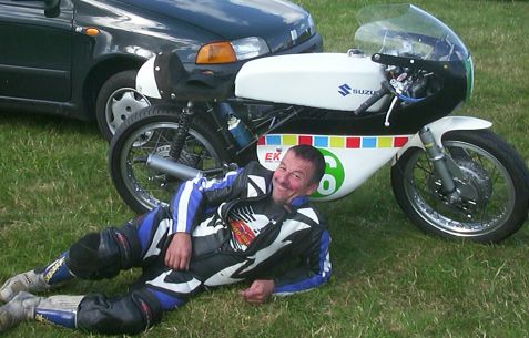
Dave relaxing after his five wins over the weekend
No wonder he looks so content with life!
Back to top
22) Dyno testing
The engine performed superbly in the first season - always starting up straight away, reliable and powerful. I had spent a lot of time and money on the bottom end, but had quickly assembled the top end without measuring compression, squish, port timing,
anything!
I had a new and unused set of barrels (tuned by Ron
Fahron 7 years ago) on a spare engine I had picked up, and some Stan Stephens tuned ones that were late arriving (my fault - I gave out the wrong phone number amongst other reasons!). I had used the Fahron 5-port barrels (with CR125 pistons) throughout the season and these were fitted when I had it dyno'd.
I had no idea at all of what the output of my engine was, but decided to measure it before fiddling with anything. However, before doing so I whipped of the heads and (finally!) measured the squish. It was too big at about 1.5mm. Removing the head gaskets made it a little too small at 0.75 (ish) mm. I decided to get the bike dyno'd in its 'with gaskets' state that I had raced it in, and then 'without gaskets' that I thought would increase the bhp due to better squish and increased compression.
The results are shown below:
The blue line is as raced.
The red line is without head gaskets.
Max bhp? - 46.1bhp at 10,200rpm (at the
back wheel). Quite impressive I thought!
However, much to my surprise it was worse without the
head gaskets. I'm not sure why yet as it didn't
appear to be leaking and it also weakened the mixture which
was a little too rich in the 'as raced' state.
The Power band is very narrow and triples from a pathetic 10bhp at 7400rpm to 30bhp at 8000rpm. This is very noticeable on the track, as if you are just off the bottom of the power band at any time, you get overtaken pretty quickly!
Future Plans
In 2002 I wrote:
I was pleased with 46.1bhp, but hope that there is more to come. The top T20 guys in the UK (with Nicasil lined TR250 replica barrels) are getting (they claim) 57-59bhp, AND with a wider rev range. 61bhp has been achieved by one or two, although I was told that this made the engine far too peaky for short circuit racing - I'll bet it did!
So how far can I expect to go on my budget? If I can get 53bhp I will be very happy. That is my target for next year. How will I get there? No idea! I have a lot to learn, a lot of experimenting to do and a lot of cash to burn through.
Well, with Lea Gourlay's tuning skills and help I've now got a reliable engine that easily achieves my original 53bhp target. However, for the start of the 2007 season my bike will have a TZ Yamaha crank, aluminium lined nicasil plated barrels (standard T20 castings) and, Lea claims, a very flexible engine producing 60+bhp! It should pull from just over 8000rpm, peak somewhere past 11000 and rev out to 13000rpm. I'd be doubtful, but Lea has recently tuned a T20 for a Manx GP rider, and in dyno testing this did exactly what he claimed, albeit with better cooling than mine as it had TR250 replica cylinders and heads. Cooling will be a problem on my bike, but we'll see what we can do. I'd like some TR barrels and heads, but haven't found a source of these yet. If all goes well we'll get my new engine dyno'd and I'll get the figures up online.
It sure should be fun on the track though!
Back to top
23) The 2002 season - some results
In all, I managed to make 5 meetings - the last three of the CRMC meetings, a Grantham Pegasus meeting at Cadwell and finally, The Plum Pudding Meeting on 26th December at Mallory park, run by the New Era Racing Club. My bike ran superbly in all!
Below are details of my first two meetings.
NB DNF's are not include in the figures
Lydden: A CRMC Meeting.
(Read all about this meeting in My First Race Meeting section above.)
| Race number |
Position in
250cc class |
Position in
race overall |
My Fastest
Lap time (s) |
| 1 |
4th of 6 |
13th of 16 |
54.31 |
| 2 |
3rd of 5 |
10th of 16 |
53.53 |
| 3 |
2nd of 5 |
10th of 19 |
52.25 |
| 4 |
3rd of 5 |
12th of 17 |
52.59 |
|
|
At this meeting, the 250 twins ran with the 350cc twins - mostly Honda K4s. There were only 6 entrants in the 250cc class, two T20's, a YDS3 Yamaha, two Ariel Arrows and a CB72 Honda.
The fastest lap of the meeting on a 250cc bike was 50.50s by Dave Brown (Suzuki T20)
|
|
Anglesey: A CRMC Meeting.
| Race number |
Position in
250cc class |
Position in
race overall |
My Fastest
Lap time (s) |
| 1 |
3rd of 3 |
8th of 13 |
57.88 |
| 2 |
3rd of 3 |
7th of 13 |
58.35 |
| 3 |
3rd of 4 |
7th of 16 |
58.36 |
| 4 * |
4th of 4 |
15th of 16 |
61.38 |
There was a low turnout for this meeting and we ran with the 250cc singles - Ducatis, Greeves', Cottons and BSAs. The fastest lap of the meeting on a 250cc twin was 55.33s by Steve Clark (Suzuki T20)
* This race the plug fouled and swing arm broke!! - see Swingarm section above.
|
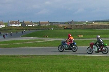
This is when the plug had packed up!
|
Back to top
This page is a good record of my journey from a rusty T20 owner to 250cc twins Championship winner and I update it whenever I get the time. I do keep making changes to the bike and they will all be duly recorded here eventually. It has been great fun receiving so many positive emails from all around the world and the number of readers that I have met at racetracks around the UK is beyond belief. I love meeting and hearing from people that have enjoyed my site and if you can get to a CRMC race meeting, please come and say hello - you'll be made very welcome.
All the best
Adrian Baker
If you are interested in Suzuki T20's and would like to add to this page, advertise a service, or just
want to say hello, Then please
send me an E-mail.
Version 3.7 February 2007. © Adrian Baker